
Operator`s manual

technical reference
317Synrad Firestar t-Series operator’s manual
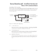
User I/O connections
Output signals
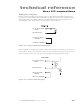
Firestar’s five user outputs correspond to the status functions described below. Outputs are optoisolated, bi-
directional analog switches that allow for high-side or low-side switching. The shared connection, Output
Common, is separate from the laser’s chassis ground to allow high-side or low-side switching and to isolate
control signals for optimum EMI performance.
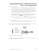
Firestar’s optically-isolated outputs are useful for sending laser status to a Programmable Logic Controller
(PLC) or computerized control system. Each of the five outputs can source 50 mA at ±24 VDC maximum
for a total load of 250 mA. For controlling larger loads, use these outputs to drive control relays.
Note: Laser Ready and Shutter Open outputs indicate separate functions. The Laser Ready output
(RDY LED On) may close while the Shutter Open output is open (SHT LED Off), but RF boards
are disabled until Laser Ready and Shutter Open outputs are closed (RDY and SHT LEDs On).
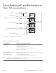
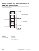
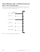
Pin 6 Laser Active
This bi-directional switched output is internally connected to Pin 13, Output Common, when
the laser is actively lasing (LASE indicator red). This output is open (high impedance) when no
beam is being emitted (LASE indicator Off). Refer to Table 3-5 for output circuit specifications.
Pin 7 Over Temperature
This bi-directional switched output is internally connected to Pin 13, Output Common, when
laser temperature is above safe operating limits (TMP indicator red). The output is open (high
impedance) when laser temperature is within operating limits (TMP indicator green). After an
over temperature fault occurs, cool the laser and then cycle DC power to reset the laser. Refer to
Table 3-5 for output circuit specifications.
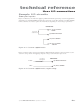
Pin 8 Laser Ready
This bi-directional switched output is internally connected to Pin 13, Output Common, when
the laser is enabled (RDY indicator yellow), indicating that lasing will occur when a PWM Com-
mand signal is applied to Pin 9 and Pin 1. When this output is initially switched closed, there is
a five-second delay during which lasing is inhibited. This output is open (high impedance) when
the laser is disabled (RDY indicator Off). Refer to Table 3-5 for output circuit specifications.
Pin 13 Output Common
Use this pin to complete the return (ground) path for any output connection (Pin 6, 7, 8, 14, or
15). The Output Common line is protected by a 0.3 A self-resetting fuse.
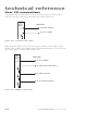
Pin 14 Shutter Open
This bi-directional switched output is internally connected to Pin 13, Output Common, when
the Shutter Switch is Open and a Shutter Open Request signal is present (SHT indicator blue),
indicating that lasing may be enabled if other operating conditions are met. The output is open
(high impedance) when the Shutter Switch is Closed or the Shutter Open Request signal is re-
moved. When the Shutter Open output closes (SHT indicator blue), there is a five-second delay
until PWM inputs are recognized. Refer to Table 3-5 for output circuit specifications.
Pin 15 Interlock Open
This bi-directional switched output is internally connected to Pin 13, Output Common, when
remote interlock circuitry is open (INT indicator red), indicating that lasing is disabled. The
output is open (high impedance) when lasing is enabled (INT indicator green). See Table 3-5 for
output circuit specifications.