
Operator`s manual

technical reference
320 Synrad Firestar t-Series operator’s manual
User I/O connections
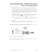
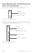
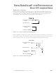
A Programmable Logic Controller (PLC) can also drive Firestar inputs. Figure 3-13 shows a typical
method for connecting to a PLC output module when only one Firestar input is used.
Figure 3-13 PLC driven interlock signal
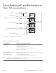
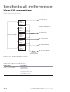
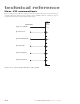
When multiple PLC outputs are used, connect Firestar inputs to the PLC as shown in Figure 3-14. By
supplying voltage (+VDC) to Pin 11, Input Common, and pulling individual inputs to ground, each input
can be independently activated by the PLC’s output module.
USER I/O PINS
(3) REMOTE INTERLOCK
(11) INPUT COMMON
PLC
DC
OUTPUT
MODULE
+V
(+5–24V)
Figure 3-14 Multiple PLC driven inputs
PLC
DC
OUTPUT
MODULE
+V
(+5–24V)
USER I/O PINS
(11) INPUT COMMON
(2) REMOTE RESET/STA RT REQUEST
(3) REMOTE INTERLOCK
(10) SHUTTER OPEN REQUEST