
Operator`s manual


technical reference
323Synrad Firestar t-Series operator’s manual
DB-9 connections
(SA models only)
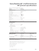
The side-mounted DB-9 connector on SA model lasers provides a Shutter Switch input as well as auxil-
iary +5 and +24 VDC power. This connector also provides Lase, Shutter, and Ready signals for driving
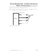
customer-supplied LEDs. Figure 3-18 illustrates DB-9 pinouts.
Caution
possible
equipment
damage
+24 VDC (Pin 4 and Pin 5) voltage outputs are not fused or electri-
cally protected. Do not short these pins; internal circuitry may be
damaged.
Pin 5
Pin 1
Pin 6Pin 9
Figure 3-18 DB-9 connector pinouts
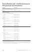
Table 3-6 describes the function of each pin on the DB-9 connector.
Table 3-6 Side-mounted DB-9 pin descriptions
Pin Function Description
1 Lase
This output activates when the laser is actively lasing (LASE indicator illuminates red).
This output is only capable of driving an LED for indication purposes. Do not attempt to
drive any other electrical device. Figure 3-19 shows how the Lase output is used.
2 No Connection
3 DC Power Ground
This connection provides a ground (earth) connection for Pin 4 and Pin 5 (+24 VDC Fan
Power), and Pin 9 (+5 VDC Auxiliary Power). This pin is the only DB-9 pin connected
to chassis ground. Do not use this pin if DC power is supplied from an external customer-
supplied DC power source.