
Operator`s manual


technical reference
324 Synrad Firestar t-Series operator’s manual
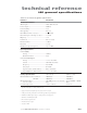
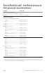
DB-9 connections
(SA models only)
Pin Function Description
4 + 24 VDC Fan Power
This connection provides +24 VDC for driving a customer-supplied cooling fan. The +24
VDC Fan Power output (Pin 4) can source up to 0.75 A max. This pin is not protected
or fused; the control board will be damaged if this pin is inadvertently shorted. The return
(ground) path must be through Pin 3, DC Power Ground.
5 + 24 VDC Fan Power
This connection provides +24 VDC for driving a customer-supplied cooling fan. The +24
VDC Fan Power output (Pin 5) can source up to 0.75 A max. This pin is not protected
or fused; the control board will be damaged if this pin is inadvertently shorted. The return
(ground) path must be through Pin 3, DC Power Ground.
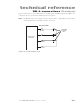
6 Shutter
This output activates when the shutter, if equipped, is Open (SHT indicator illuminates
blue), indicating that lasing may be enabled if other operating conditions are met. This
output is only capable of driving an LED for indication purposes. Do not attempt to drive
any other electrical device. Figure 3-19 shows how the Shutter output is used.
7 Ready
This output activates when the laser is enabled (RDY indicator illuminates yellow), indi-
cating that, after a five-second delay, lasing will occur when a PWM Command signal is
applied provided that other operating conditions are met. This output is only capable of
driving an LED for indication purposes. Do not attempt to drive any other electrical device.
Figure 3-19 shows how the Ready output is used.
8 Shutter Switch
In keyswitch models, this input connects to the physical Shutter Switch. Leave this input
open to enable lasing. Grounding this pin indicates that the shutter is Closed, which
disables lasing. If connecting an external shutter switch to Pin 8, the circuit path must be
grounded to Pin 3, DC Power Ground. There is a five-second delay imposed from the time
the shutter input is opened to the time that PWM Command signals are accepted.
9 + 5 VDC Auxiliary Power
This connection provides +5 VDC for driving external inputs or outputs. The +5 VDC
Auxiliary Power output (Pin 9) can source up to 0.5 A maximum and is protected by a self-
resetting fuse. The return (ground) path must be through Pin 3, DC Power Ground.