
Operator`s manual


technical reference
325Synrad Firestar t-Series operator’s manual
DB-9 connections
(SA models only)
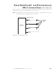
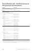
Figure 3-19 shows how to connect LED indicators to Ready, Lase, and Shutter outputs. The DB-9 circuit
is designed so that no external current-limiting resistors are required.
Note: The Shutter output circuit is designed to drive only blue, white, or purple LEDs. You must add an
external 43 Ohm resistor if an LED of another color is used.
DB9 OUTPUT PINS
(1) LASE
(6) SHUTTER
(7) READY
(9) +5 VDC
DB9 OUTPUT
CIRCUITRY
CUSTOMER
SUPPLIED
LEDs
Figure 3-19 DB-9 output circuit