
Operator`s manual


technical reference
326 Synrad Firestar t-Series operator’s manual
Integrating Firestar safety features
The Integrating Firestar safety features section includes subsections:
■ Keyswitch functions
■ Shutter functions
■ Remote Interlock functions
Firestar’s DB-15 User I/O connector allows system integrators or end-users to integrate Firestar safety fea-
tures into their control system. Firestar’s keyswitch, shutter, and remote interlock functions serve to enable
or disable DC power to Firestar’s RF drive. Without DC power, the RF driver cannot supply RF energy to
the resonator, causing the CO
2
gas to remain in a zero-energy state. Firestar status indicators provide users
with a quick visual indication of the laser’s operational status. All power to the laser’s RF board is removed
whenever RDY or SHT indicators are Off (Laser Ready or Shutter Open outputs open).
Keyswitch functions
Keyswitch lasers
After DC power-up or after a remote interlock fault, the Keyswitch must be toggled OFF/ON to reset the
laser and enable the RDY LED, signaling that DC power is applied to the RF driver. Over temperature
faults are reset by removing, then reapplying DC power after the laser has cooled.
For Keyswitch-equipped lasers used in automated systems, this keyswitch/reset function is available via the
Remote Reset/Start Request input on Pin 2 of the User I/O connector. To use this “remote keyswitch”
functionality, first place the Keyswitch in the ON position. Then after each DC power-up cycle (or to reset
a fault condition), apply a momentary voltage pulse in the range of ±5–24 VDC to Pin 2, the Remote
Reset/Start Request input. Removing voltage allows DC power to reach the RF driver and begins a five-
second delay after which lasing is enabled (RDY LED illuminates yellow). The RF driver is disabled as long
as voltage is applied to Pin 2.
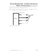
Your control system can monitor the laser’s ready status on the User I/O connector by connecting your
system’s input between Pin 8, Laser Ready, and Pin 13, Output Common (see Figure 3-17). The Laser
Ready output closes when the laser is enabled (RDY LED illuminated yellow), indicating that lasing is
possible. The output is open ( in a high-impedance state) and the RDY LED is off when lasing is disabled.
Note: After the Laser Ready output closes, a five-second delay occurs before lasing is enabled.
OEM lasers
On OEM lasers, the RDY LED illuminates on DC power-up (provided that Shutter Open Request and
Remote Interlock inputs are enabled) and five seconds later, DC power is applied to the RF driver. Over
temperature faults are reset by removing and then re-applying DC power after the laser has cooled. Remote
interlock faults are not latched; the RDY LED illuminates yellow as soon as the interlock circuit is closed
(when the INT LED turns from red to green) and five seconds later lasing is enabled.
Although a Remote Reset/Start Request input is not needed to reset OEM faults, it can be used to
inhibit (disable) lasing. Disable the laser by applying a voltage in the range of ±5–24 VDC to Pin 2, the
Remote Reset/Start Request input. Removing voltage allows power to reach the RF driver and begins
a five-second countdown after which lasing is enabled (RDY LED illuminates yellow). The RF driver is
disabled as long as voltage is applied to Pin 2.
Your control system can monitor the laser’s ready status on the User I/O connector by connecting your
system’s input between Pin 8, Laser Ready, and Pin 13, Output Common (see Figure 3-17).