
Operator`s manual


technical reference
327Synrad Firestar t-Series operator’s manual
Integrating Firestar safety features
The Laser Ready output closes when the laser is enabled (RDY LED illuminated yellow), indicating that
lasing is possible. The output is open (in a high-impedance state) and the RDY LED is off when lasing is
disabled.
Note: After the Laser Ready output closes, a five-second delay occurs before lasing is enabled.
Shutter functions
A mechanical Shutter Switch is installed on all Keyswitch-equipped lasers. Lasing is enabled when the shut-
ter is Open (SHT LED illuminated blue) and disabled when the shutter is Closed (SHT LED off). The
SHT LED illuminates blue to indicate that DC power is applied to the RF driver.
For t-Series OEM and Keyswitch-equipped lasers in automated systems, the shutter function is provided by
the Shutter Open Request signal via Pin 10 on the User I/O connector. To use this “remote shutter”, first
place the Shutter Switch (if equipped) in the Open position and then apply a voltage in the range of ±5–24
VDC to Pin 10, Shutter Open Request. This input signal causes the SHT LED to illuminate and sends
DC power to the RF driver, enabling lasing after a five-second delay. Lasing is disabled until the manual
Shutter Switch is placed in the Open position and a Shutter Open Request signal is applied to Pin 10.
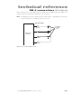
Your control system can monitor the laser’s shutter status on the User I/O connector by connecting your
system’s input between Pin 14, Shutter Open, and Pin 13, Output Common (see Figure 3-17). The Shut-
ter Open output closes when the Shutter Switch is Open and a Shutter Open Request signal is present
(SHT LED illuminated blue). The output is open (in a high-impedance state) and the SHT LED is off
when the Shutter Switch is Closed or the Shutter Open Request signal is removed.
Note: After the Shutter Open output closes, a five-second delay occurs before lasing is enabled.
Remote interlock functions
Interlock circuits are often used to disable machinery when a shield, panel, or door is opened. Firestar’s re-
mote interlock function allows you to connect into an external remote interlock circuit and prevent lasing
by removing DC power from the laser’s RF driver boards when the circuit is electrically “open”.
Lasing is enabled when a Remote Interlock signal is present (INT LED illuminated green), if RDY and
SHT LEDs are illuminated and disabled when the Remote Interlock signal is removed (INT LED red,
RDY LED off). DC power is applied to the RF driver only when the INT LED is green and the RDY LED is
yellow (and the SHT LED is illuminated blue). Remote interlock functionality is provided by the Remote
Interlock signal via Pin 3 on the User I/O connector.
To use Firestar’s remote interlock feature, apply a voltage in the range of ±5–24 VDC to Pin 3, Remote
Interlock. Applying an interlock signal causes the INT LED to illuminate green and sends DC power to
the RF driver, which enables lasing after a five-second delay (provided that the RDY LED is yellow and the
SHT LED is blue). Removing the interlock signal removes DC power from the RF driver, causing the INT
LED to turn red and the RDY LED to turn off. Lasing remains disabled until a Remote Interlock signal is
reapplied to Pin 3.
Your control system can monitor the laser’s remote interlock status on the User I/O connector by connect-
ing your system’s input between Pin 15, Interlock Open, and Pin 13, Output Common (see Figure 3-17).
This output is closed when remote interlock circuitry is open (INT indicator illuminated red). The output
is open (in a high-impedance state) and the INT LED is green when interlock circuitry is closed.
Note: After the Interlock Open output opens, a five-second delay occurs before lasing is enabled.