August 1973 FORM: OM-313 Effective with serial No. 72-61 2483 MODEL MODEL/STOCK NO. SERIAL/STYLE NO. OWNERS Two Fifty Twin Two Fifty Twin-P STOCK NO. 901 973 901 976 DATE PURCHASED MANUAL MILLER ELECTRIC MFG. CO. APPLETON, WISCONSIN, USA 54911 ADDITIONAL COPY PRICE 60 CENTS NWSA CODE NO. 4579 U.S ...
TABLE OF CONTENTS Page No. Paragraph No. SECTION 1 SAFETY RULES FOR OPERATION OF ARC WELDING MACHINE 1-1. General 1 -2. Welding 1 -3. Electrode Holder 1 Cables 1 1 4. Code Conformance - 1 1 1 -5. Parallel Connections 1 1 1 6. Power Disconnect Switch - 1-7. 1 1 Polarity Switch Range Switch 8. - 1 1 9. Exhaust Gases - 1 1-10. Power Circuit Ground 2 1-11. Containers Which Held Combustibles 2 1-12. Hollow Castings (Welding of) 1-13. Explosion Hazards 2 1-14. Ventilation 2 1-15.
SECTION 1 - 1- SAFETY RULES FOR OPERATION OF ARC WELDING MACHINE 1. GENERAL These rules apply to ac and dc welding generators. ac trans former and ac/dc welding machines, and dc transformer recti fier welding machines. In arc-welding operations, where electrically energized parts exposed, observe the following safety rules to insure max imum personal safety and protect nearby persons.
When you know the container held not readily dissolve in water: -~ 1. Clean out thouroughly with a steam liquid or gas or a which will cleansing agent and purge all air or inert with a gas such as carbon dioxide or nitrogen before repairing. Carbon dioxide is heavier than air and will tend opening is at the top. 2. 3. Use steam Use or 4.
1-15. SOLVENTS Do electrode on the table top metallic surface. (Figure 1-7) greasing, Do not weld where ultraviolet light from the electric arc can containing even minute amounts of vapors from as trichloroethylene or perchloroethylene. Ul traviolet light can decompose the vapors to form phosgene, a highly toxic gas and other irritating products. penetrate air ~olvents such 1-16. FIRE HAZARDS weld DONT near can flammable or combustible materials.
Keep a clean cover glass in front of the filter plate for the protection thereof. Frequent renewal of these cover glasses is necessary, since they become covered with spatter, reducing vision. Whenever it is necessary to grind or chip metal, wear protec. tive goggles specifically designed for this purpose. Serious eye injuries may result from failure to wear protective goggles. 1-25. COMPRESSED GAS CYLINDERS 1-22. CLOTHING NEVER NEVER use inadequate, poor, or worn-out clothing.
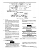
SECTION 2-INTRODUCTION . Model Welding Mao. Rated Current Open Wsldieg Ranges Ciruuit Current Amperes Vollugo Amperes Amperes Input At Ruled LoS Output 60Hz. Oimensions hoe kw 45 20.7 11.8 35 16.1 8.2 208)260 Vults 230 Volts 460 Volts 103 90 go io 78 65 34 15.6 11.8 ~y 5~ 25 11.5 8.2 Inches) 250W 30 Volts, Power 30% Outy Cycle 200 @ ec Poctor Low 25-125 oc 78 dc dc 25051 Low 20-88 75 30 Volts.
~ldi ng p owe r the front and ~e should be loca ted so PRIMARY CABLE PRIMARY VOLTAGE INPUT HOLE JUMPER LINKS that panels with the air vents are clear of any obstruction. Cooling air is drawn in through the front upper air vent and expelled Out of the rear panel rear air vent. The location should be such that a minimum amount of dust and dirt will be drawn into the air stream.
Use Table 3-2 as a guide for selecting the Correct welding cable size (or the anticipated maximum weld current that will be used. Table 3-2 takes into account the total cable for the weld circuit. This means the combined length of th~ Elec 6. trode cable that connects the Electrode Holder to the weld ing. power source and the Work cable between the welding power source and the work piece. For example: If the Elec trode cable is 75 feet long and the work cable is 25 feet long, 7.
The amount exact of desired welding current within the 4-5. range chosen can be selected by rotating the Fine Current Control on the front of the welding power source. The Cur rent Indicator on the front panel will show the current selec ted. When reading the Current Indicator for the amperage selected, 4-3. that the scale ensure amperage range being shows the output voltage available at limits of the minimum and maximum Fine Current Contro! setting.
6-2. TRANSFORMER FAN MOTOR 6-3. Occasional blowing out of the dust and firt from around the transformer is recommended. This should be done periodi cally depending upon the location of the unit and the amount of dust and dirt in the atmosphere. A clean dry air stream should be used for this cleaning operation. All models are equipped with an exhaust fan and rely on forced draft for adequate cooling for high duty cycles and overloads.
August 1973 FORM: OM-313 MODEL MODELJSTOCK NO. SERIAL/STYLE NO. DATE PURCHASED PARTS LIST .11 msuuer MILLER ELECTRIC MFG. CO. APPLETON, WISCONSIN, USA 54911 NWSA CODE NO. 4579 STOCK NO.
Quantity Models Item Dia. Factory No. Mkgs. Part No. Figure A Description 1 014 632 Figure B WRAPPER PANEL 7 Ti 027280 7 Ti 027281 (See Page 2) TERMINAL BOARD ASSEMBLY, primary (See Fig. C Page 3) REACTOR & SHUNT (See Fig. E Page 4) SPRING, indicator band BAND, indicator TRANSFORMER, power (See Fig. D Page 3) TRANSFORMER, power (See Fig.
Item Dia. Factory No. Mkgs. Part No. Figure B Quantity Description Assembly, Rear (See Fig. A Page 1 Item 2) - Panel FM 30 032603 *024 601 MOTOR, fan 1 (consisting of) 2 BEARING 31 019073 WINDTUNNEL 1 32 010489 1 33 032 612 34 014 623 35 038 315 SPACER, mtg rectifier BLADE, fan PANEL, rear BOARD, junction diode leads RECTIFIER, main (consisting of) RESISTOR, 1000 ohm 5 watt SUPPRESSOR, 1 uf 2.
Item Factory No. Part No. 038 934 Terminal Board 41 WJS 662 BOAI-LL), mtg 42 038 618 43 038 887 44 45 010 910 601 835 Figure C - Assy, Primary (See Fig.
Dia. Factory No. Mkgs. Part No. Figure E 027 283 Description Reactor & Shunt (See zl 76 **027 282 77 **027 191 78 **027 192 79 * *027 230 80 020 284 81 020 301 82 605 129 83 020 300 84 605 144 85 027 691 86 010 188 87 010 370 88 010 189 89 010 369 90 601 869 91 605 063 92 010 256 93 027 215 Fig. A Page 1 Item Quantity 4) - Item - .
Item Factory No. Fart No. Figure El 027 215 Z Description Shunt (See Fig. E Page 4 Item Quantity 93) 1 101 027 673 SCREW, 102 024 785 COLLAR 2 103 027 672 601 860 105 028 108 106 027 674 107 605 609 108 010 072 109 605 618 110 602 176 111 604 633 BLOCK, travel shunt NUT,hex8-32 BLOCK, shunt PLATE, lock SCREW, machine fiat hd 10-32 x 1-1/2 BEARING, thrust 7/16 ID x 3/4 OD x 1/16...
Item Dia. Factory No. Mkgs. Part No. Figure F Panel 121 Quantity Description Assembly, Front (See Fig. A Page 1 Item 11) NAMEPLATE 124 Si *025 865 125 S2 027925 (order by stock, model & serial number) BEARING, nylon PANEL, front SWITCH, 2PST 60 ampere SWITCH, current selector (See Fig.
Item Factory No. Part No. Figure Fl 027 925 Quantity Description Switch, Current Selector (See Fig. F Page 6 Item 125) 146 019 603 KNOB 147 604 318 NUT, 148 010 805 HANDLE 149 011 950 011 951 CONTACT, CONTACT, 150 024 694 BEARING 151 103 634 152 104 935 BOARD, glastic mtg components BRACKET, mtg switch GUIDE, molded HANGER, Minerallac No.1 PLATE ASSEMBLY, movable (consisting of) * 1 hex - self locking 1/4-20 1 .
r