OM-196 188K July 2003 Processes MIG (GMAW) Welding Pulsed MIG (GMAW-P) Flux Cored (FCAW) Welding Automatic Welding Description Automatic Welding Interface And Arc Welding Power Source Operating Instructions and Programming Instructions for Auto Invision II Visit our website at www.MillerWelds.
From Miller to You Thank you and congratulations on choosing Miller. Now you can get the job done and get it done right. We know you don’t have time to do it any other way. That’s why when Niels Miller first started building arc welders in 1929, he made sure his products offered long-lasting value and superior quality. Like you, his customers couldn’t afford anything less. Miller products had to be more than the best they could be. They had to be the best you could buy.
TABLE OF CONTENTS WARNING This product, when used for welding or cutting, produces fumes or gases which contain chemicals known to the State of California to cause birth defects and, in some cases, cancer. (California Health & Safety Code Section 25249.5 et seq.) SECTION 1 – SAFETY PRECAUTIONS - READ BEFORE USING . . . . . . . . . . . . . . . . . . . . . . . . . . . . 1-1. Symbol Usage . . . . . . . . . . . . . . . . . . . . . . . . . . . . . . . . . . . . . . . . . . . . . . . . . . . . . . . . . . . . .
TABLE OF CONTENTS SECTION 8 – INTRODUCTION TO PROGRAMMING . . . . . . . . . . . . . . . . . . . . . . . . . . . . . . . . . . . . . . . 8-1. Pulse MIG Programs . . . . . . . . . . . . . . . . . . . . . . . . . . . . . . . . . . . . . . . . . . . . . . . . . . . . . . . . . . 8-2. Standard Pulse Welding Programs . . . . . . . . . . . . . . . . . . . . . . . . . . . . . . . . . . . . . . . . . . . . . . . 8-3. Program 1 – 1.2 mm Steel (.045”), 98-2 Argon-Oxy . . . . . . . . . . . . . . . . . . . . . . . . . .
TABLE OF CONTENTS SECTION 14 – SETUP . . . . . . . . . . . . . . . . . . . . . . . . . . . . . . . . . . . . . . . . . . . . . . . . . . . . . . . . . . . . . . . . . 14-1. Setup Flow Chart . . . . . . . . . . . . . . . . . . . . . . . . . . . . . . . . . . . . . . . . . . . . . . . . . . . . . . . . . . . . . 14-2. Using Setup Displays . . . . . . . . . . . . . . . . . . . . . . . . . . . . . . . . . . . . . . . . . . . . . . . . . . . . . . . . . . 14-3. Selecting Or Changing Access Code . . . . . . . . .
Declaration of Conformity For European Community (CE) Products Miller Electric Mfg. Co. Manufacturer’s Name: Manufacturer’s Address: Declares that the product: 1635 W.
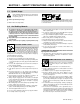
SECTION 1 – SAFETY PRECAUTIONS - READ BEFORE USING som _nd_4/98 1-1. Symbol Usage Means Warning! Watch Out! There are possible hazards with this procedure! The possible hazards are shown in the adjoining symbols. Y Marks a special safety message. . Means “Note”; not safety related. This group of symbols means Warning! Watch Out! possible ELECTRIC SHOCK, MOVING PARTS, and HOT PARTS hazards. Consult symbols and related instructions below for necessary actions to avoid the hazards. 1-2.
ARC RAYS can burn eyes and skin. Arc rays from the welding process produce intense visible and invisible (ultraviolet and infrared) rays that can burn eyes and skin. Sparks fly off from the weld. D Wear a welding helmet fitted with a proper shade of filter to protect your face and eyes when welding or watching (see ANSI Z49.1 and Z87.1 listed in Safety Standards). D Wear approved safety glasses with side shields under your helmet.
1-3. Additional Symbols For Installation, Operation, And Maintenance FIRE OR EXPLOSION hazard. MOVING PARTS can cause injury. D Do not install or place unit on, over, or near combustible surfaces. D Do not install unit near flammables. D Do not overload building wiring – be sure power supply system is properly sized, rated, and protected to handle this unit. D Keep away from moving parts such as fans. D Keep all doors, panels, covers, and guards closed and securely in place.
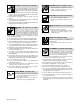
1-5. EMF Information Considerations About Welding And The Effects Of Low Frequency Electric And Magnetic Fields Welding current, as it flows through welding cables, will cause electromagnetic fields. There has been and still is some concern about such fields.
SECTION 1 – CONSIGNES DE SECURITE – LIRE AVANT UTILISATION som _nd_fre 4/98 1-1. Signification des symboles Signifie Mise en garde ! Soyez vigilant ! Cette procédure présente des risques de danger ! Ceux-ci sont identifiés par des symboles adjacents aux directives. Y Identifie un message de sécurité particulier. . Signifie NOTA ; n’est pas relatif à la sécurité.
LES RAYONS DE L’ARC peuvent provoquer des brûlures dans les yeux et sur la peau. Le rayonnement de l’arc du procédé de soudage génère des rayons visibles et invisibles intenses (ultraviolets et infrarouges) susceptibles de provoquer des brûlures dans les yeux et sur la peau. Des étincelles sont projetées pendant le soudage. D Porter un casque de soudage muni d’un écran de filtre approprié pour protéger votre visage et vos yeux pendant le soudage ou pour regarder (voir ANSI Z49.1 et Z87.
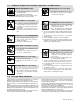
1-3. Dangers supplémentaires en relation avec l’installation, le fonctionnement et la maintenance Risque D’INCENDIE OU D’EXPLOSION. DES ORGANES MOBILES peuvent provoquer des blessures. D Ne pas placer l’appareil sur, au-dessus ou à proximité de surfaces infllammables. D Rester à l’écart des organes mobiles comme le ventilateur. D Maintenir fermés et fixement en place les portes, panneaux, recouvrements et dispositifs de protection.
1-4. Principales normes de sécurité Safety in Welding and Cutting, norme ANSI Z49.1, de l’American Welding Society, 550 N.W. Lejeune Rd, Miami FL 33126 Safety and Health Sandards, OSHA 29 CFR 1910, du Superintendent of Documents, U.S. Government Printing Office, Washington, D.C. 20402. Recommended Safe Practice for the Preparation for Welding and Cutting of Containers That Have Held Hazardous Substances, norme AWS F4.1, de l’American Welding Society, 550 N.W.
SECTION 2 – DEFINITIONS 2-1. Manufacturer’s Warning Label Definitions Warning! Watch Out! There are possible hazards as shown by the symbols. 1 1.1 1.2 1.3 2 1 1.1 1.2 1.3 2.1 2.2 2.3 2 2.1 2.2 2.3 3 3.1 3 3.1 3.2 3.2 3.3 3.3 4 4 4.1 + 5 + + 4.1 6 + 5 6 S-179 310 Electric shock from welding electrode or wiring can kill. Wear dry insulating gloves. Do not touch electrode with bare hand. Do not wear wet or damaged gloves.
1 2 3 1 2 3 4 5 6 4 V V > 60 s 5 V S-179 190-A 6 Warning! Watch Out! There are possible hazards as shown by the symbols. Electric shock from wiring can kill. Disconnect input plug or power before working on machine. Hazardous voltage remains on input capacitors after power is turned off. Do not touch fully charged capacitors. Always wait 60 seconds after power is turned off before working on unit, OR Check input capacitor voltage, and be sure it is near 0 before touching any parts.
2-2. Symbols And Definitions A V Amperage Positive Remote Voltage Output Circuit Breaker Negative On Off Inductance Protective Earth (Ground) Voltage Input 2-3. Manufacturer’s Rating Label S-184 765 2-4. Harmonic Data HARMONIC DATA per IEC 61000-3-12, draft 2000-9-29 PRIMARY; 400V/30.5A/60hz LOAD; 450A/38Vdc/390IPM/,MAXIMUM OUTPUT, GMAW. R sce = 227.28 THD 61 Amps PWHD 35 Amps Table 4, balanced three phase equipment.
SECTION 3 – INSTALLATION 3-1. Specifications Input Power Rated Welding Output Voltage Range Wire Diameter Range Wire Feed Speed Range* Maximum OpenCircuit Voltage DC Amperes Input At Rated Load Output 60 Hz, Three-Phase KVA KW 450 A @ 38 Volts DC, Standard: .030 To .062 in 100% Duty Cycle; 10 – 38 95 31 21.6 50 To 780 ipm (0.8 To 1.6 mm) 565 A @ 43 Volts DC, (1.3 To 19.8 mpm) 60% Duty Cycle *Wire feed speed ranges are for GMAW welding.
3-3. Selecting A Location 2 Movement Tipping Y Do not move or operate unit where it could tip. 3 OR 1 Location 1 Y Special installation may be required where gasoline or volatile liquids are present – see NEC Article 511 or CEC Section 20. 5 Lifting Forks Use lifting forks to move unit. Extend forks beyond opposite side of unit. 2 Lifting Handles Use handles to lift unit. 3 4 18 in (460 mm) Hand Cart Use cart or similar device to move unit.
3-5.
3-7. Electrical Service Guide Three-Phase Input Voltage 400 Input Amperes At Rated Output 31 Max Recommended Standard Fuse Or Circuit Breaker Rating In Amperes 45 Min Input Conductor Size In AWG/Kcmil 10 Max Recommended Input Conductor Length In Feet (Meters) 264 (80) Min Grounding Conductor Size In AWG/Kcmil 10 Reference: 1993 National Electrical Code (NEC). S-0092J 3-8. Connecting Input Power Input Filter Board L1 L2 =GND/PE Y Always connect grounding conductor first.
3-9. Rear Panel Connections 1 1 2 3 2 B C A D E To connect interconnecting cord to receptacle, align keyway, insert plug, and tighten threaded collar. M L K J P NT R S FG Secure ring terminal on remaining end of cord to work. H 4 Peripheral Receptacle Receptacle provides connection to touch sensor, water flow switch, jog +/–, and n/o relay contacts circuitry.
3-10. Peripheral Receptacle Functions Function Socket Socket Information A Contact closure to B dependent upon state of programmed output (see Section 14-5). The closure between A and B can carry a maximum of 0.6 amps at 125 VAC; or a maximum of 0.6 amps at 110 VDC. B Contact closure to A dependent upon state of programmed output (see Section 14-5). See socket A information for current carrying capacity of closure. C* Circuit common.
3-11. Touch Sensor Operation The touch sensor feature allows the robot to locate a weldment using the wire feed system and welding power source. Voltage sense leads provide a path for touch sensor voltage when this feature is turned on at the peripheral receptacle. Turning on touch sensor causes a dc voltage to be present on the welding wire.
3-13. Connecting Setup Pendant To Welding Power Source Y Turn Off welding power source and weld control. 1 2 3 1 . Disconnect the setup pendant from the welding Welding Power Source Interconnecting Cord Setup Pendant To make connections, align plug with receptacle, insert plug, and use thumb screws on receptacle to secure plug. power source before welding.
SECTION 4 – OPERATION 4-1. Operational Terms The following is a list of terms and their definitions as they apply to this interface unit: General Terms: Adaptive Pulse Welding When the “adaptive pulse” welding process is selected, the unit will attempt to automatically regulate pulse frequency in order to maintain a constant arc length, regardless of change in welding wire stickout. Abk (Background Amperage) Abk is the low weld current. Background current preheats welding wire and maintains the arc.
System Reset By selecting system reset in the memory reset mode, the unit defaults to original factory settings for all programs and all set up excluding System, Arc Time, and Model Type. Voltage (Control Feedback) Allows voltage to be monitored at the output terminals by two methods. This can be selected through the internal connections of the unit, or through the unit’s external voltage sense lead. When using the V.
4-4. Upper Front Panel Controls 8 1 1 Setup Pendant Receptacle Receptacle for connecting interconnecting cord. 2 2 3 4 pendant Jog Forward Push Button 4 5 6 Jog Reverse Push Button Retracts wire up into the gun. 5 Gas Indicator LED LED lights when gas solenoid is energized. Advances wire out of the gun. 6 3 Momentarily energizes gas solenoid to purge air from gun shielding gas line, or to adjust shielding gas regulator.
4-5. Duty Cycle And Overheating Duty Cycle is percentage of 10 minutes that unit can weld at rated load without overheating. If unit overheats, thermostat(s) opens, output stops, and cooling fan runs. Wait fifteen minutes for unit to cool. Reduce amperage or duty cycle before welding. Y Exceeding duty cycle can damage unit and void warranty.
4-7. Setup Pendant Controls 1 2 8 4 3 5 7 6 802 815 1 Increase Button Works with security feature on welding power source to allow increasing weld parameter values within the allowable range. 2 Decrease Button Works with security feature on welding power source to allow decreasing weld parameter values within the allowable range. OM-196 188 Page 24 3 Parameter Select Button Press button to move indicator in right window display, and to make selections in setup screens.
SECTION 5 – MAINTENANCE & TROUBLESHOOTING 5-1. Routine Maintenance Y Disconnect power before maintaining. . Maintain more often during severe conditions. 3 Months Replace damaged or unreadable label. Repair or replace cracked cables. Replace cracked torch body. Repair or replace cracked cables and cords. 6 Months Clean and tighten weld terminals. Blow out inside. 5-2. Blowing Out Inside Of Unit Y Do not remove case when blowing out inside of unit.
5-3. Removing Case and Measuring Input Capacitor Voltage Y Significant DC voltage can remain on capacitors after unit is Off. Always check the voltage as shown to be sure the input capacitors have discharged before working on unit. 1 Tools Needed: 5/16 in 1 Turn Off welding power source, and disconnect input power. 1 Outside Handle Screws To loosen top, remove two outside handle screws from both handles and all side bolts.
5-4. Voltmeter/Ammeter Help Displays . All directions are in reference to the front of the unit. All circuitry referred to is located inside the unit. 1 Help 1 Display Indicates a malfunction in the primary power circuit. If this display is shown, contact a Factory Authorized Service Agent. 2 Help 2 Display Help 3 Display Indicates the left side of the unit has overheated. The unit has shut down to allow the fan to cool it (see Section 4-5). Operation will continue when the unit has cooled. 4 A HE.
5-5.
5-6. Weld Interface Board PC12 Diagnostic LED’s 1 LED2 LED8 LED4 LED10 LED11 LED6 LED1 LED3 LED5 LED7 LED9 Weld Interface Board PC12 Diagnostic LED’s are visible inside unit, located on PC12 (see illustration for board location). LED12 Refer to Section 5-7 for information on diagnostic LED’s. Reinstall cover and left side panel after checking diagnostic LED’s.
5-7. Diagnostic LED’s On Weld Interface Board PC12 LED Status 1 On Indicates auxiliary output relay is not energized. Off Indicates auxiliary output relay is energized. On Indicates gas valve is not energized. Off Indicates gas valve is energized. 3 On Indicates +24 volts dc is present for gas valve. Off Indicates +24 volts dc is not present for gas valve. 4 On Indicates +15 volts dc is present on weld interface board PC12.
5-8. Customer Interface Board PC14 Diagnostic LED’s 1 Customer Interface Board PC14 Diagnostic LED’s are visible inside unit, located on PC14 (see illustration for board location). Refer to Section 5-9 for information on diagnostic LED’s. Reinstall top cover after checking diagnostic LED’s.
5-9. Diagnostic LED’s On Customer Interface Board PC14 LED 1 2 3 4 5 6 7 8 9 10 11 12 13 14 15 16 17 18 19 Status Diagnosis On Indicates –15 volts dc RA supply is present on customer interface board PC14. Off Indicates –15 volts dc RA supply is not present on customer interface board PC14. On Indicates +15 volts dc RA supply is present on customer interface board PC14. Off Indicates +15 volts dc RA supply is not present on customer interface board PC14.
LED Status 23 On Input signal On from peripheral for jog advance. Off Input signal Off from peripheral for no jog advance. On Input signal On from peripheral for jog retract. 24 25 26 Diagnosis Off Input signal Off from peripheral for no jog retract. On Input signal On from peripheral for shielding gas purge. Off Input signal Off from peripheral for no shielding gas purge. On Input signal On for touch sensor. Off Input signal Off for no touch sensor. 5-10.
5-11. Diagnostic LED’s On Motor Board PC13 LED Status Diagnosis 1 On Indicates motor reverse relay is energized. Red Off Indicates motor reverse relay is not energized. 2 On LED should be On. Indicates 115 volts ac input is sufficiently charging +170 volts dc bus for motor. Red Off If LED is Off, check 115 volts ac input. 9 On LED should be On. Indicates +15 volts dc regulated bus is on.
Notes OM-196 188 Page 35
SECTION 6 – ELECTRICAL DIAGRAMS Figure 6-1.
203 505-A OM-196 188 Page 37
Figure 6-2.
203 311 (1 of 3) OM-196 188 Page 39
Figure 6-3.
203 311 (2 of 3) OM-196 188 Page 41
Figure 6-4.
203 311 (3 of 3) OM-196 188 Page 43
Figure 6-5.
190 696 OM-196 188 Page 45
184 183 Figure 6-6. Circuit Diagram For Interconnect Board PC2 188 015 Figure 6-7.
Notes OM-196 188 Page 47
Figure 6-8.
193 709-A OM-196 188 Page 49
Figure 6-9.
191 838 OM-196 188 Page 51
Figure 6-10.
212 354-A OM-196 188 Page 53
182 996 Figure 6-11.
200 739 Figure 6-12.
Figure 6-13.
191 843-A (Part 1 of 2) OM-196 188 Page 57
Figure 6-14.
191 843-A (Part 2 of 2) OM-196 188 Page 59
Figure 6-15.
Pensar 86147s03 (Part 1 of 3) OM-196 188 Page 61
Figure 6-16.
Pensar 86147s03 (Part 2 of 3) OM-196 188 Page 63
Figure 6-17.
Pensar 86147s03 (Part 3 of 3) OM-196 188 Page 65
174 578-A Figure 6-18.
200 739-A Figure 6-19.
200 739 Figure 6-20.
191 531 Figure 6-21.
Figure 7-1. Complete Assembly OM-196 188 Page 70 84 85 86 81 87 83 82 1 81 80 79 78 6 2 77 7 8 76 5 90 74 71 10 11 72 75 73 9 92 70 66 63 65 64 69 12 68 13 89 69 67 46 45 14 15 44 16 18 20 61 52 51 50 49 62 9 48 47 17 19 60 21 53 23 58 57 54 25 22 59 56 24 55 27 26 30 28 42 32 31 88 43 29 33 35 36 37 38 39 40 41 91 34 SECTION 7 – PARTS LIST . Hardware is common and not available unless listed.
Item No. Dia. Mkgs. Part No. Description Quantity Figure 7-1. Complete Assembly . . . 1 . . . . . . . . . . . . . . . . 185 970 . . . 2 . . . . . . . . . . . . . . . . 195 585 . . . 5 . . . . . . . . . . . . . . . . 179 310 . . . 6 . . . . . . . . . . . . . . . . 183 827 . . . 7 . . . . HD1 . . . . . . 168 829 . . . . . . . . . PLG19 . . . . . 115 094 . . . 8 . . . . . . . . . . . . . . +179 902 . . . 9 . . . . . . . . . . . . . . . . 185 836 . . . 10 . . . . . T1 . . . . . . . 185 524 . . . 11 . . . .
Item No. Dia. Mkgs. Part No. Description Quantity Figure 7-1. Complete Assembly (Continued) . . . 47 . . . . . T2 . . . . . . . 185 231 . . . . . . . . . . RC10 . . . . . . 166 679 . . . 48 . . . . . . . . . . . . . . . . 180 105 . . . 49 . . . . . . . . . . . . . . +194 449 . . . 50 . . . . RC2 . . . . . . 604 176 . . . . . . . . . . . . . . . . . . . . . . 175 282 . . . 51 . . . . CB1 . . . . . . 161 078 . . . 52 . . . . CB2 . . . . . . 093 995 . . . 53 . . . . . . . . . . . . . . . . 179 847 . . .
Item No. Dia. Mkgs. Part No. Description Quantity Figure 7-1. Complete Assembly (Continued) . . . . . . . . . . . . . . . . . . . . . . 144 844 . . . . . . . . . . . . . . . . . . . . . . 091 772 . . . 88 . . . . . . . . . . . . . . . . 208 478 . . . 89 . . . . . . . . . . . . . . . . 179 276 . . . 90 . . . . . . . . . . . . . . . . 199 840 . . . 91 . . . . . . . . . . . . . . . . 196 261 . . . 92 . . . . PC7 . . . . . . 206 776 . . . STAND-OFF, No. 6-32 x .875 . . . . . . . . . . . . . . . . . . . .
Notes OM-196 188 Page 74
OM-196 188K July 2003 Programming Instructions for Auto Invision II
SECTION 8 – INTRODUCTION TO PROGRAMMING 8-1. Pulse MIG Programs The interface unit is designed for use in pulse MIG welding (adaptive or standard), or MIG welding. . Selecting hardwire or softwire is done during setup (see Section 14) Program Hardwire Selected Softwire Selected 1 .035” Steel, Argon – Oxy .045” 4043, Argon 2 .045” Steel, Argon – Oxy .045” 5356, Argon 3 .035” Steel, Argon – CO2 .035” 4043, Argon 4 .045” Steel, Argon – CO2 .035” 5356, Argon 5 .
8-3. Program 1 – 1.2 mm Steel (.045”), 98-2 Argon-Oxy Wire Size/Type: 1.2 mm (.045”) Steel Gas: Ar - Oxy / 19 L/min (40 CFH) MPM / IPM Apk Abk PPS PWms Vpk 19.1 / 750 540 159 263 3.1 34.5 17.8 / 700 530 150 250 3.0 33.9 16.5 / 650 520 141 237 2.9 33.3 15.2 / 600 510 133 225 2.9 32.7 14.0 / 550 500 124 212 2.8 32.0 12.7 / 500 490 115 200 2.8 31.4 11.4 / 450 480 110 187 2.7 31.0 10.2 / 400 470 105 175 2.7 30.6 8.9 / 350 460 100 162 2.6 30.2 7.
8-5. Program 3 – 1.2 mm Steel (.045”), 80-20 Argon-CO2 Wire Size/Type: 1.2 mm (.045”) Steel Gas: Ar - CO2 / 19 L/min (40 CFH) MPM / IPM Apk Abk PPS PWms Vpk 19.1 / 750 570 134 246 2.9 41.2 17.8 / 700 560 130 235 2.9 40.6 16.5 / 650 550 126 224 2.9 40.0 15.2 / 600 540 123 213 2.9 39.5 14.0 / 550 530 119 201 2.8 38.9 12.7 / 500 520 115 190 2.8 38.3 11.4 / 450 502 107 177 2.7 37.4 10.2 / 400 485 100 165 2.7 36.6 8.9 / 350 467 92 152 2.6 35.7 7.
8-7. Program 5 – 1.0 mm 316 (.040”), 98-2 Argon-CO2 Wire Size/Type: 1.0 mm (.040”) 316 Gas: Ar - CO2 / 19 L/min (40 CFH) MPM / IPM Apk Abk PPS PWms Vpk 19.1 / 750 443 144 183 2.6 34.0 17.8 / 700 425 130 175 2.5 33.8 16.5 / 650 407 116 167 2.4 33.6 15.2 / 600 390 103 160 2.3 33.4 14.0 / 550 372 89 152 2.2 33.1 12.7 / 500 355 75 145 2.1 32.9 11.4 / 450 351 71 136 2.0 32.7 10.2 / 400 348 68 128 2.0 32.5 8.9 / 350 344 64 119 1.9 32.3 7.
8-9. Program 7 – 1.0 mm 308L (.040”), 98-2 Argon-CO2 Wire Size/Type: 1.0 mm (.040”) 308L Gas: Ar - CO2 / 19 L/min (40 CFH) MPM / IPM Apk Abk PPS PWms Vpk 19.1 / 750 436 120 183 2.5 34.2 17.8 / 700 425 115 175 2.4 33.7 16.5 / 650 414 110 167 2.3 33.2 15.2 / 600 403 105 160 2.3 32.7 14.0 / 550 391 100 152 2.2 32.1 12.7 / 500 380 95 145 2.1 31.6 11.4 / 450 370 86 136 2.0 31.1 10.2 / 400 360 78 128 2.0 30.6 8.9 / 350 350 69 119 1.9 30.3 7.
8-11. Program 1 – 1.2 mm Metal Core (.045”), 95-5 Argon-CO2 Note The next 8 programs are available after changing software wiretype (see Section 14-10). Wire Size/Type: 1.2 mm (.045”) Metal Core Gas: Ar - CO2 / 19 L/min (40 CFH) MPM / IPM Apk Abk PPS PWms Vpk 19.1 / 750 525 160 211 2.9 31.6 17.8 / 700 515 155 205 2.9 31.3 16.5 / 650 505 150 199 2.9 31.0 15.2 / 600 495 145 193 2.9 30.8 14.0 / 550 485 140 186 2.8 30.5 12.7 / 500 475 135 180 2.8 30.3 11.
8-13. Program 3 – 1.2 mm ER 4043 (.045”), Argon Wire Size/Type: 1.2 mm (.045”) ER 4043 Gas: Ar / 19 L/min (40 CFH) MPM / IPM Apk Abk PPS PWms Vpk 17.9 / 705 492 160 190 2.9 31.6 17.8 / 700 490 160 190 2.9 31.5 16.5 / 650 451 167 195 2.8 30.1 15.2 / 600 412 174 200 2.8 28.8 14.0 / 550 373 180 205 2.7 27.4 12.7 / 500 334 187 210 2.7 26.1 11.4 / 450 316 169 196 2.6 26.1 10.2 / 400 298 151 183 2.5 26.1 8.9 / 350 279 133 169 2.3 26.1 7.
8-15. Program 5 – 1.0 mm 5356 (.040”), Argon Wire Size/Type: 1.0 mm (.040”) 4043 Gas: Ar / 19 L/min (40 CFH) MPM / IPM Apk Abk PPS PWms Vpk 18.6 / 735 410 75 156 1.3 27.0 18.5 / 730 410 75 156 1.3 27.0 17.7 / 695 407 69 152 1.3 26.9 16.9 / 665 405 64 148 1.3 26.8 16.1 / 630 402 58 144 1.3 26.6 15.2 / 600 400 52 140 1.3 26.5 13.8 / 540 369 51 134 1.3 26.2 12.4 / 485 338 51 128 1.3 26.0 11.0 / 430 306 50 122 1.2 25.7 9.7 / 380 275 50 116 1.
8-17. Program 7 – .8 mm Steel (.030”), 98-2 Argon-Oxy Wire Size/Type: .8 mm (.30”) Steel Gas: Ar - Oxy / 19 L/min (40 CFH) MPM / IPM Apk Abk PPS PWms Vpk 19.7 / 775 384 121 143 2.0 33.9 17.8 / 700 375 110 135 1.9 33.6 15.9 / 625 366 99 127 1.8 33.3 14.0 / 550 358 88 120 1.7 33.0 12.1 / 475 349 76 112 1.6 32.6 10.2 / 400 340 65 104 1.5 32.3 8.9 / 350 334 56 94 1.5 31.8 7.6 / 300 328 48 85 1.5 31.3 6.4 / 250 321 39 75 1.4 30.7 5.
8-19. Setup Pendant Mode Select Button 1 2 Mode Display Mode Select Button Press Mode Select button to move indicator in left window display. Go to Section 8-20. 1 > Process Sequence SharpArc Card Process > Sequence SharpArc Card > Prg 1 Pulse 035” Steel Argon – Oxy 2 Ref.
8-20. Setup Pendant Parameter Select Button 1 2 Parameter Display Moving Line Moving line is under value that can be changed. 3 Pulse Panel Parameter Select Button Press pulse panel parameter select button to move indicator in right window display. 2 1 > Process Sequence SharpArc Card > Prg 1 Pulse 035” Steel Argon – Oxy Prg 1 > Pulse 035” Steel Argon – Oxy Pulse 035” Steel Argon – Oxy > Teach Off 3 Ref.
8-21. Setup Pendant Parameter Increase And Decrease Buttons Use mode select button to select mode to be changed (see 8-19). Use pulse panel parameter select button to select parameter to be changed (see 8-20). 1 Increase Button Press button to increase value that is underlined by the moving line. 2 Decrease Button Press button to decrease value that is underlined by the moving line.
SECTION 9 – GETTING STARTED FOR PULSE WELDING 9-1. Weld Cycle For Pulse Welding . The type of robot connected determines what combination of parameters are available. Start Power Wire Speed Robot Motion Weld Time Crater Time Start Speed Retract Time Weld Speed Preflow Time Weld Start Crater Speed Run-In WFS Run-In Setting Arc Strike Weld Stop Postflow Time Arc Out Time Ref. S-0271 9-2.
9-3. Setting Weld Sequence Display Set Desired Weld Sequence Trim 1 1 Weld Weld Parameters Display Parameter ranges are as follows: Trim (Arc Length), 0-99 > 50 Trim 200 IPM Wire Feed Speed, 50-780 Inches Per Minute, IPM Increase/ Decrease Go to Section 9-4. Parameter Select Set Desired Weld Sequence Wire Feed Speed Weld 60 Trim > 200 IPM Increase/ Decrease Parameter Select > Weld 60 Trim 300 IPM Increase Proceed to next Section. 9-4. Setting Crater Sequence Display 1 1 >Cratr 0.
9-5. Setting Postflow Sequence Display 1 > Poflw 0.0 Sec Poflw > 0.0 Sec Parameter Select Set Desired Time Increase/ Decrease > Poflw 1.2 Sec 1 Postflow Parameters Display Postflow can be adjusted from 0-9.9 seconds. If value set is zero (0), there is no Postflow sequence. Parameter Select Increase Proceed to next Section. SECTION 10 – TEACHING A PULSE WELDING PROGRAM NOTE See GMAW-P (Pulsed MIG) Process Guide supplied with unit for more information. 10-1.
10-2. Teach Points Explained IPM 780 750 700 650 600 550 Example Of A Synergic Setting For 425 IPM With All Teach Points Set At 50 IPM Increments 500 450 400 350 300 250 Apk Abk 200 PPS 150 PWms Vpk 100 50 150 10 30 1 2.5 180 20 55 210 30 80 240 40 105 5 7.5 10 270 50 130 300 60 160 330 70 185 12.5 15 17.5 2 The teach mode allows the user to create custom pulse MIG welding programs. The teach mode has 15 teach points.
10-3. Selecting Teach Point Wire Feed Speed For Pulse Welding Program 1 1 2 2 > Process Sequence SharpArc Card > Prg 1 Pulse 035” Steel Argon – Oxy Use parameter select button to select Teach. > Teach Off Use increase/decrease buttons to select On. Parameter Select 3 Increase/ Decrease IPM (Teach Point) The parameters associated with this wire feed speed teach point can be modified. The wire feed speed value itself cannot be changed from the set point.
10-4. Setting Teach Point Parameters For Pulse Welding Program Increase/ Decrease > Process Sequence SharpArc Card Teach On > 450 IPM 28.1 Vpk 340 Apk Teach On 450 IPM > 28.1 Vpk 340 Apk Or Teach On 450 IPM > 31.2 Vpk 340 Apk Parameter Select Parameter Select 1 Increase/ Decrease Increase/ Decrease 31.2 Vpk 343 Apk > 92 Abk 160 PPS 31.2 Vpk 343 Apk > 70 Abk 160 PPS 450 IPM 31.2 Vpk > 343 Apk 70 Abk 450 IPM 31.
NOTE Make copies of this chart for future use. Program # Wire Size/Type Gas Program Name Card # Gun Model Flowrate IPM Preflow: Apk Abk PPS PWms Vpk Sec. Run-In Trim: IPM: Sec.: Crater Trim: IPM: Sec.: Postflow: OM-196 188 Page 94 Sec.
10-5. Changing To Adaptive Pulse Welding Welding parameters are the same for both a Pulse and an Adaptive Pulse welding program. While welding adaptively, the unit uses feedback to attempt to maintain a constant arc length. To change to Adaptive Pulse welding, proceed as shown: Mode Select 1 1 > Process Sequence SharpArc Card Setup Pendant Display Default display when unit is first turned On, at other times use mode select button to select Process.
11-2. Changing To Mig Welding 1 Mode Select Setup Pendant Display Default display when unit is first turned On, at other times use mode select button to select Process. 1 Go to Section 11-3. > Process Sequence SharpArc Card > Prg 1 AdaptPulse 035” Steel Argon – Oxy Parameter Select > Process Sequence SharpArc Card Prg 1 > AdaptPulse 035” Steel Argon – Oxy Prg 1 > MIG > Process Sequence SharpArc Card Increase/ Decrease 11-3.
11-4. Setting Start Sequence Display 1 1 Start Parameters Display Parameter ranges are as follows: > Start 24.0 Volt 90 IPM 0.2 Sec Start > 18.0 Volt 90 IPM 0.2 Sec Parameter Select Start 18.0 Volt > 200 IPM 0.2 Sec Set Desired Voltage Set Desired Wire Feed Speed Parameter Select Seconds, 0-2.5 Sec. If value set is zero (0), there is no Run-In sequence. With zero (0) time value, programmed values for volts and wire feed speed are used until a valid arc condition is detected. Volts, 10.0-38.
11-6. Setting Crater Sequence Display 1 > Cratr 0.02 Sec 24.0 Volt 90 IPM Crater Parameters Display Parameter ranges are as follows: 1 Seconds, 0-2.50 Sec. If value set is zero (0), there is no Crater sequence. Volts, 10.0-38.0 Volts. Parameter Select Wire Feed Speed, 50 to 780 inches per minute, IPM. Go to Section 11-7. Cratr > 0.12 Sec 24.0 Volt 90 IPM Set Desired Time Cratr 0.12 Sec > 18.0 Volt 90 IPM Parameter Select Cratr 0.12 Sec 18.
11-8. Setting Postflow Sequence Display 1 1 > Poflw 0.0 Sec Poflw > 0.0 Sec Parameter Select > Poflw 1.2 Sec Set Desired Time Postflow Parameters Display Postflow can be adjusted from 0-9.9 seconds. If value set is zero (0), there is no Postflow sequence. Parameter Select Increase/ Decrease 11-9. Setting Run-in Sequence Display .
SECTION 12 – SETTING SharpArcE CONTROL 12-1. Selecting And Adjusting SharpArcE Control 1 SharpArc SharpArc is used to adjust arc cone width and arc characteristics. Use mode select button to move > to select SharpArc. Use Display Control to adjust Arc setting. > Process Sequence SharpArc Card > Prg 1 Pulse 035” Steel Argon – Oxy SharpArc setting range is from 0 to 20. The factory default is set at zero (0).
SECTION 13 – USING THE OPTIONAL DATA CARD 13-1. Installing Data Card 1 Label 1 2 3 4 5 6 7 8 9 11 10 12 13 THIS SIDE UP 60-M Data Card 14 Peel backing from label and apply to data card with THIS SIDE UP by metal pins. Write the names of the programs stored on the card on the label. Write the name of the piece of equipment the card is used with on the label. 2 Data Card 3 Card Slot Insert card into slot. To format card, turn On power to the unit. Select Card from menu.
13-2. Using The Data Card Use Mode Select button to select Card. 1 Process Sequence SharpArc > Card 1 Card Display 2 Write Used to transfer program data from unit to card. The program card can hold up to 32 programs. When writing to the card, the next available program number is automatically assigned. Press Below 3 Parameter Select Once Read Used to transfer program data from card to unit. 4 Delete Used to delete program data from card. 2 5 4 5 OM-196 188 Page 102 Used to exit card display.
13-3. Naming Programs And Writing To Card NOTE All program types (Pulse, Adaptive Pulse, and MIG) can be stored on a data card and retrieved. Setup and Control menus do not save to the card. 1 Process Sequence SharpArc > Card Press Below 2 > Write Read Delete Done Parameter Select #1 Pulse 035” Steel Argon – Oxy Press Parameter Select Allowable characters include: 0 thru 9, :, ;, <, =, >, ?, @, A thru Z, [, , ], ^, _,‘, a thru z , blank , !, ”, #, $, %, &, ’, (, ), *, +, –, .
13-4. Reading From Card NOTE Programs developed on the Auto Invision will not run the same on Auto Invision II.
13-5. Reading (Or Deleting) From An Empty Card 1 1 Write > Read Delete Done Warning Display If there are no programs on the card, this series of displays appear. WARNING: Card Empty Press Below Parameter Select Once Write Read Delete > Done >Process Sequence SharpArc Card Press > Prg 2 MIG Parameter Select 13-6. Deleting Programs From Card Use Mode Select button to select Card.
13-7. Selecting Security Lock NOTE Security lock works only when a data card is inserted. 1 Security Display Use this display to lock a program’s weld parameters so that changes can not be made using pulse panel controls. Access Setup Display 1 Sequence SharpArc Card > Security 3 Prog 2 > Lock Off Increase With lock on a program, the operator cannot change parameters of that program.
SECTION 14 – SETUP 14-1. Setup Flow Chart 1 Example Setup Pendant Display Display Selection >Access Access Mig Type Aux Out Voltage Features Code > Volt Min 10.0 Volt 2 3 Settings Default Section Off/On Off 14-3 DVC On/Off Off 14-4 1 2 3 To set up features that customize operation, use the setup displays.
14-2. Using Setup Displays 1 3 2 2 Mode Parameter Select Select Front Panel Setup Display Front panel display during setup. 3 Pulse Panel Mode And Parameter Select Buttons Power Switch On Rear Panel Press and hold down both buttons while turning On unit. 4 Setup Pendant Display Follow this procedure any time access is required. Once in the setup displays, use the Mode Select button to select a particular display.
14-3. Selecting Or Changing Access Code NOTE Access code works only when a data card is inserted (see Section 13). 1 Access Setup Display Code Display With code off, access to the setup displays is not restricted. 1 With code on, the operator must know and enter the access code to access or change any of the setup displays.
14-4. Selecting Voltage Correction 1 Access > Mig Type Aux Out Voltage Access Setup Display MIG Voltage Correction > DVC Off 1 Mig Type Display With DVC Voltage Correction On, the unit uses closed-loop feedback or voltage sensing leads to maintain set voltage parameters. With DVC Voltage Correction Off, feedback from the arc is not used for closed-loop feedback to maintain voltage parameters. Feedback from the arc is still used for other functions.
14-7. Selecting Arc Start Method NOTE Arc Start selection is not used when welding in non-pulsed MIG. Do not use the Hot Start setting for .035 in (9 mm) or smaller wire. 1 Access Setup Display Standard Start Welding operation is performed at set values for welding parameters. 2 Press Mode Select Aux Output Voltage > ArcStart Arc Time Hot Start Use the Hot Start mode for pulse welding when high initial weld current is necessary to start large diameter welding wires.
14-9. Selecting Units For Wire Feed Speed And Motor Type 1 Wire Feed Display The displayed unit of wire speed (IPM or MPM) can be changed along with the wire feed motor type (Standard, Low Speed, or High Speed).
14-10. Selecting Wire Type NOTE If wire type is changed, perform a system reset (see Section 14-12) immediately after selecting wire type to bring up the correct welding programs. . After using system reset to store wire type selection into memory, all other setup parameters return to factory default settings. See Section 14-2 for procedure to return to setup displays and reset parameters.
14-12. Resetting Memory 1 1 Press Mode Select Access Setup Display Wiretype Display > Memory Shutdown > No Reset 2 3 > Process Sequence SharpArc Card 2 Parameter Select > Prg 1 Pulse 035” Steel Argon – Oxy Increase/ Decrease 4 3 > System Reset System Reset Press Parameter Select button to reset programs and setup to original factory settings. System, Arc Time, and Robot Control settings are not affected by the system reset. If setup card is in card slot, program will be loaded from card.
14-14. Selecting Program Name Feature 1 Access Setup Display Name Display When a data card is used, the programs written from the unit to the card can be named. Press Mode Select 1 Memory Shutdown > Name Program Card Programs > On Card Programs > Off Increase 14-15. Remote Program Select 1 Program Display When Program is On, a remote device or robot Teach Pendant may be used to select programs (see Section 14-16). When Off, program selection must be done from Setup Pendant.
14-17. Jog Wire Feed Speed Selection 1 Jog IPM Display Jog wire feed speed can be varied between 50 and 780 inches per minute, IPM. Access Setup Display When not welding, a Robot Jog local setting will jog wire at the Local Jog ipm setting, even if robot provides wire jog signal. Press Mode Select 1 Name Program > Jog IPM Flow A Robot Jog remote setting requires that the robot provide a jog command and jog speed signal.
14-19. Arc Voltage Error Selection 1 Access Setup Display . When a system reset is done, Monitor is set to Off. Press Mode Select When this feature is off, arc voltage or arc length variations will not cause an error or shut the unit down. 1 Jog IPM Flow > Monitor Stick Monitor Display Provides a means to enable/disable the arc voltage error feature and to set an acceptable range of deviation from set arc voltage or arc length (trim) before the error will actuate. Arc Volts > On 2.0 Volts 1.
14-21. Setting Ramps Function 1 Access Setup Display 1 2 Monitor Stick > Ramps Exit > Prog 1 Start Crater Prog 2 > Start Crater 3 Start Display Crater Display Turns crater ramping On or Off as defined. > Prog 2 Start Crater Off Off Off Off Parameter Select 3 Prog 2 Start > Crater Off Off 4 On Off Program Number Choose the desired program number (1 through 8). Turns start and/or crater ramping On or Off as desired.
SECTION 15 – CONTROL MENU The control menu allows the user access to rise time setting that controls rise and fall time of the pulse square wave. Changing the rise time setting changes the square wave shape by rounding off the corners, and makes it possible to quiet the pulse arc by just changing the rise time. 15-1. Using Menu Display 1 3 2 2 Increase Button Front Panel Control Display Front panel display during control setting.
15-2. Setting Rise Time Parameter NOTE Maximum Rise Time setting will make the welding power source go to its maximum output in the maximum amount of time (1250 amperes per millisecond). 1 1 A/ms > Rise Time Adaptive AutoConfig Retract Access Control Display Rise Time Display Setting is depend on desired arc characteristics. Make a sample weld after each setting until desired arc characteristics are obtained. Use Increase or Decrease button to change setting.
15-4. Setting Auto Configure Parameter 1 1 Rise Time Adaptive > AutoConfig Retract Access Control Display Auto Configure Display Setting allows user to do manual configuration or automatic configuration by welding power source/interface. > On None Use Increase or Decrease button to change setting. Press Mode Select button to go to next parameter or cycle power off and back on at power switch to save setting and exit Control menu.
15-5. Setting Retract On/Off 1 Adaptive AutoConfig > Retract ShrpStrt Access Control Display 1 > Retract On Use Increase or Decrease button to change setting. If the retract feature is turned On, a weld sequence step is added in the process screens. Press Mode Select Increase/ Decrease >Process Sequence SharpArc Card > Prg 1 Pulse 035” Steel Argon – Oxy Power Switch Retract Display Settings allow user to turn the retract feature On or Off.
15-7. Exiting The Control Menu 1 AutoConfig Retract ShrpStrt > Exit Access Control Display Exit Cntrl Menu Now 1 Exit Control Menu Display Allows the user to leave the control menu.
Effective January 1, 2002 (Equipment with a serial number preface of “LC” or newer) This limited warranty supersedes all previous Miller warranties and is exclusive with no other guarantees or warranties expressed or implied. Warranty Questions? Call 1-800-4-A-MILLER for your local Miller distributor. Your distributor also gives you ... Service You always get the fast, reliable response you need. Most replacement parts can be in your hands in 24 hours.
Owner’s Record Please complete and retain with your personal records. Model Name Serial/Style Number Purchase Date (Date which equipment was delivered to original customer.) Distributor Address City State Zip For Service Call 1-800-4-A-Miller or see our website at www.MillerWelds.com to locate a DISTRIBUTOR or SERVICE AGENCY near you. Always provide Model Name and Serial/Style Number.