
Use and Care Manual


16
joint or union using a small paintbrush. If any bubbling is
observed, the connection is not sealed adequately and
must be retightened. Repeat the tightening and soap
check process until bubbling ceases.
IMPORTANTNOTE:Whenpressuretestinggassupply
linesatpressuresgreaterthan1/2psig(14inchW.C.),
thegassupplypipingsystemmustbedisconnected
fromthefurnacetopreventdamagetothegascontrol
valve.Ifthetestpressureislessthanorequalto1/2
psig(14inchW.C.),closethemanualshut-offvalve.
required that you measure the gas input rate. This may
be accomplished in the usual way, by clocking the gas
meter and using the local gas heating value. To check the
input of the furnace see page 21.
IMPORTANTNOTE:Observetheactionoftheburners
tomakesurethereisnoyellowing,liftingorashback
oftheame.
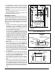
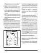
ConvertingtoLPGas
TheCMF2furnaceisshippedfromthefactoryforusewith
natural gas but can be converted to use liquid propane
gas.UsethefollowingprocedureandFigure12(page17)
for converting the gas burner.
1. SetthermostattoOFF.
2. Turn off all power to the furnace.
3. Openfurnacedoorandlocatethegasvalve.
4. PushinonthegasknobandturnittoOFF.
5. Shut off gas supply at meter.
6. Disconnect gas burner electric cord, gas piping to
burner, and thermostat leads.
7. Remove nuts securing burner in place.
8. Disconnect inlet pipe union at burner.
9. Disconnect the two wires leading to gas control valve.
10.Removebolts securingU-shaped manifoldplate to
orifice assembly.
11. Remove the main orifice and replace it with the correct
LP fuel orifice as shown in Table 4. Refer to the rating
plate on the furnace to determine the firing rate for
your application. NOTE: If the firing rate of your furnace
has been converted, make sure the appropriate LP
orifice for the new firing rate is installed.
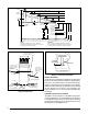
12. Remove the regulator converter on top of the gas valve.
Invert the converter so that the red ring will be located
at the bottom and the LP stamping on the converter
appears up.
13. Screw converter back into the regulator, hand tight
plus 1/8 turn.
14. Reinstall the burner assembly into the furnace.
15. Reconnect the gas piping and electrical wires to the
gas valve.
16.Openthemanualshut-offvalveandfollowtheOperating
Instructions outlined on page 20.
HighAltitudeApplication
Installation of this furnace at altitudes above 2,000 feet
shall be in accordance with local codes, or in the absence
oflocalcodes,theNationalFuelGasCode,ANSIZ223.1/
NFPA54orNationalStandardofCanada,NaturalGas&
PropaneInstallationCodeCGAB149.1.Pleaseconsult
your local code authority.
WARNING:
Thereductionofinputratingnecessaryforhigh
altitudeinstallationmayonlybeaccomplished
withfactorysuppliedorices.Donotattemptto
drilloutoricesintheeld.Improperlydrilled
orices may cause re, explosion, carbon
monoxidepoisoning,personalinjuryordeath.
TheCMF2 furnaceisshippedfromthe factorywithits
orifices and gas regulator setting for natural gas operation
atsealevelaltitudes.At2,000feet,theNFGCrequires
that this appliance be derated 4% for each 1,000 feet of
altitude.Forexample,theinputneedstobereduced8%
at 2,000 feet, 12% at 3,000 feet, etc. This deration is in
reference to the input rate and gas heating value at sea
level.
Highaltitudeconversionforthisfurnacerequiresreducing
the orifice size or decreasing the manifold pressure. When
decreasing the manifold pressure, the pressure must not
besetbelow3.2inWC.Ifthepressureneedstobeset
below3.2inWCtoachieveproperderation,thenchange
the orifice size and raise the manifold pressure back to
3.5inWC.
Afterchangingtheregulatorpressureortheorices,itis
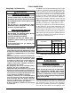
* Timesarebasedonnaturalgasatanaverageof1,000BTUpercubicfoot,aburnermanifoldpressureof3.5inWC,andameterdialsizeof1cubicfoot.
** TimesarebasedonLPgasatanaverageof2,500BTUpercubicfoot,aburnermanifoldpressureof3.5inWC,andameterdialsizeof1cubicfoot.
Table4.Natural&LPGasOrices
Burner
Designation
Firing Rate
Input (BTUH)
Natural Gas
Orice Number
Natural Gas
TimePerRev.* (sec)
LP Gas
Orice
Number
LP Gas
Time PerRev.** (sec)
GasGun-65-DI-S 65,000 24 55 43 138
GasGun-75-DI-S 75,000 20 48 40 120
GasGun-90-DI-S 85,000 18 43 37 106