OM-1308 144 212N March 1998 Processes Gas Metal Arc (MIG) Welding Flux Cored Arc (FCAW) Welding Description Arc Welding Power Source And Wire Feeder R Millermatic 250 Visit our website at www.MillerWelds.
From Miller to You Thank you and congratulations on choosing Miller. Now you can get the job done and get it done right. We know you don’t have time to do it any other way. That’s why when Niels Miller first started building arc welders in 1929, he made sure his products offered long-lasting value and superior quality. Like you, his customers couldn’t afford anything less. Miller products had to be more than the best they could be. They had to be the best you could buy.
TABLE OF CONTENTS The following terms are used interchangeably throughout this manual: MIG = GMAW SECTION 1 – SAFETY PRECAUTIONS - READ BEFORE USING . . . . . . . . . . . . . . . . . . . . . . . . . . . . 1-1. Symbol Usage . . . . . . . . . . . . . . . . . . . . . . . . . . . . . . . . . . . . . . . . . . . . . . . . . . . . . . . . . . . . . . . . 1-2. Arc Welding Hazards . . . . . . . . . . . . . . . . . . . . . . . . . . . . . . . . . . . . . . . . . . . . . . . . . . . . . . . . . . 1-3.
SECTION 1 – SAFETY PRECAUTIONS - READ BEFORE USING som _nd_5/97 1-1. Symbol Usage Means Warning! Watch Out! There are possible hazards with this procedure! The possible hazards are shown in the adjoining symbols. Y Marks a special safety message. . Means “Note”; not safety related. This group of symbols means Warning! Watch Out! possible ELECTRIC SHOCK, MOVING PARTS, and HOT PARTS hazards. Consult symbols and related instructions below for necessary actions to avoid the hazards. 1-2.
ARC RAYS can burn eyes and skin. Arc rays from the welding process produce intense visible and invisible (ultraviolet and infrared) rays that can burn eyes and skin. Sparks fly off from the weld. D Wear a welding helmet fitted with a proper shade of filter to protect your face and eyes when welding or watching (see ANSI Z49.1 and Z87.1 listed in Safety Standards). D Wear approved safety glasses with side shields under your helmet.
1-3. Additional Symbols for Installation, Operation, and Maintenance FIRE OR EXPLOSION hazard. MOVING PARTS can cause injury. D Do not install or place unit on, over, or near combustible surfaces. D Do not install unit near flammables. D Do not overload building wiring – be sure power supply system is properly sized, rated, and protected to handle this unit. D Keep away from moving parts such as fans. D Keep all doors, panels, covers, and guards closed and securely in place.
1-5. EMF Information Considerations About Welding And The Effects Of Low Frequency Electric And Magnetic Fields 1. Keep cables close together by twisting or taping them. Welding current, as it flows through welding cables, will cause electromagnetic fields. There has been and still is some concern about such fields.
SECTION 2 – INSTALLATION 2-1. Specifications Max. OpenCircuit Voltage Rated Output 250 A at 28 VDC, 40% Duty Cycle 200 A at 28 VDC, 60% Duty Cycle Amps Input at Rated Output, 50 or 60 Hz, Single-Phase 200 V 220 V 230 V 380 V 415 V 460 V 575 V KVA KW 50 2.3* 45 2.2* 44 2* 26 1.3* 24 1.2* 22 1* 18 0.8* 10 0.46* 7.7 0.13* 32 Wire Type and Diameter Solid Steel Stainless Steel Flux Cored .023 – .045 in (0.6 – 1.2 mm) .023 – .035 in (0.6 – 0.9 mm) .030 – .045 in (0.8 – 1.
2-3. Volt-Ampere Curves 1 Normal Volt-Ampere Curves The volt-ampere curves show the normal minimum and maximum voltage and amperage output capabilities of the welding power source. Curves of other settings fall between the curves shown. 1 2 Overload Volt-Ampere Curves When unit is used beyond capacity, circuitry senses the overload and shuts down unit output. Release trigger and lower weld voltage setting before trying to weld.
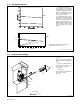
2-5. Installing Welding Gun 1 2 3 1 Drive Assembly Gun Securing Knob Gun End Loosen securing knob. Insert gun end through opening until it bottoms against drive assembly. Tighten knob. 2 4 4 Gun Trigger Plug Insert plug into receptacle, and tighten threaded collar. Close door. 3 Ref. ST-150 256-D 2-6. Setting Gun Polarity For Wire Type . Always read and follow wire manufacturer’s recommended polarity, and see label inside unit by wire drive assembly. Tools Needed: 3/4 in 2-7.
2-8. Installing Wire Spool And Adjusting Hub Tension Use compression spring with 8 in (200 mm) spools. When a slight force is needed to turn spool, tension is set. Tools Needed: 15/16 in ST-072573-B 2-9. Positioning Jumper Links Check input voltage available at site. 1 200 VOLTS 230 VOLTS Jumper Links Access Door Open door. 220 VOLTS 2 Jumper Link Label Check label – only one is on unit.
2-10.
2-12. Threading Welding Wire 1 2 3 4 5 6 7 4 Wire Spool Welding Wire Inlet Wire Guide Pressure Adjustment Knob Drive Roll Outlet Wire Guide Gun Conduit Cable Lay gun cable out straight. 7 Tools Needed: 1 2 3 5 6 . Hold wire tightly to keep it from unraveling. 4 in (102 mm) 6 in (150 mm) Open pressure assembly. Pull and hold wire; cut off end. Push wire thru guides into gun; continue to hold wire. Tighten Close and tighten pressure assembly, and let go of wire.
SECTION 3 – OPERATION 3-1. Controls 1 Wire Speed Control The scale around the control is percent, not wire feed speed. 2 2 Voltage Switch The scale around the control is actual voltage. 3 1 Low Range/Full Range Switch Use Low Range when wire speed is between 50 and 350 ipm. 4 5 Pilot Light Power Switch 3 4 5 Ref. ST-148 579-A / Ref. ST-174 835-A 3-2. Installing Receptacle Module For Use With A Spool Gun (Optional) Remove existing options panel.
SECTION 4 – MAINTENANCE AND TROUBLESHOOTING 4-1. Routine Maintenance Y Disconnect power before maintaining. 3 Months Repair or replace cracked weld cable. Replace unreadable labels. Clean and tighten weld terminals. 6 Months Blow out or vacuum inside. during heavy service clean monthly. Remove drive roll and carrier. Apply light coat of oil or grease to drive motor shaft. OR 4-2. Circuit Breaker CB1 1 Circuit Breaker CB1 If CB1 opens, wire feeding stops.
4-4. Replacing Gun Contact Tip Y Turn Off power. 1 2 Nozzle Contact Tip Cut off welding wire at contact tip. Remove nozzle. Remove contact tip and install new contact tip. Reinstall nozzle. 2 1 Tools Needed: ST-149 326-B 4-5. Changing Drive Roll And Wire Inlet Guide 5 3 1 2 2 Securing Screw Inlet Wire Guide Loosen screw. Slide tip as close to drive rolls as possible without touching. Tighten screw. 3 Anti-Wear Guide Install guide as shown.
4-8. Cleaning Or Replacing Gun Liner Tools Needed: Y Disconnect gun first. 3/8 in Head tube Remove nozzle, contact tip, adapter, and wire outlet guide. Wire Outlet Guide 3/8 in Remove liner. Lay gun cable out straight before installing new liner. Blow out gun casing. To Reassemble Gun: Insert new liner. Install and tighten wire outlet guide. Cut liner off 3/4 in (20 mm) (3/8 in [9.5 mm] for aluminum) from head tube. Install adapter, contact tip, and nozzle. Ref.
4-9. Replacing Switch And/Or Head Tube Y Disconnect gun first. 3 1 4 2 Remove handle locking nut. Secure head tube in vice. 5 Remove shock washers from front and rear of head tube. 6 Slide handle. Remove switch housing. Note: If installing new switch, push switch lead connectors onto terminal of new switch (polarity is not important). Install switch back into handle, and secure with handle locking nut. If replacing head tube, continue to end of figure. Loosen jam nut.
4-10. Troubleshooting Trouble No weld output; wire does not feed. Remedy Be sure line disconnect switch is On (see Section 2-11). Replace building line fuse or reset circuit breaker if open (see Section 2-11). Reset circuit breaker CB1 (see Section 4-2). Secure gun trigger connections (see Section 2-5). Check and replace Power switch if necessary. Have Factory Authorized Service Agent check all board connections and main control board. No weld output; wire feeds. Thermostat TP1 open (overheating).
SECTION 5 – ELECTRICAL DIAGRAM SC-175 883-A Figure 5-1.
. Hardware is common and 16 15 14 SECTION 6 – PARTS LIST 19 20 Fig 6-3 Fig 6-6 25 1 2 24 3 23 22 4 Fig 6-2 21 6 7 5 8 9 10 Fig 6-5 8 11 7 12 17 13 18 not available unless listed. ST-801 717 Figure 6-1.
Item No. Dia. Mkgs. Part No. Description Quantity Figure 6-1. Main Assembly . . . 1 . . . . . . . . . . . 148 597 . . . 2 . . . . . . . . . . . 146 168 . . . 3 . . PLG7 . . 083 526 . . . 4 . . . . . . . . . . . . Fig 6-2 . . . 5 . . . . T1 . . . 174 553 . . . 5 . . . . T1 . . . 174 554 . . . 5 . . . . T1 . . . 174 552 . . . . . . . . . TP3 . . . 121 497 . . . 6 . . . . . . . . . . . 150 387 . . . 7 . . . . . . . . . . . 602 250 . . . 8 . . . . . . . . . . . 186 758 . . . 9 . . . . Z1 . . . 143 892 . .
. Hardware is common and not available unless listed. 1 2 3 4 5 6 7 8 9 33 10 32 Fig 6-4 34 31 11 12 13 30 14 29 15 25 17 18 19 24 23 16 28 26 27 20 22 21 ST-148 325-D Figure 6-2.
Item No. Dia. Mkgs. Part No. Description Quantity Figure 6-2. Baffle, Center w/Components (Fig 6-1 Item 4) . . . 1 . . . . . . . . . . . 058 427 . . . 2 . . . . . . . . . . . 085 980 . . . 3 . . . . . . . . . . . 605 941 . . . 4 . . . . . . . . . . . 186 437 . . . 5 . . . . . . . . . . . 057 971 . . . 6 . . . . . . . . . . . 057 745 . . . 7 . . . . . . . . . . . 186 435 . . . 8 . . . . . . . . . . . 186 436 . . . 9 . . . . . . . . . . . 177 307 . . . 10 . . . . . . . . . . . 174 813 . . . . . . . . . .
Item No. Dia. Mkgs. Part No. Description Quantity Figure 6-3. Panel, Front w/Components (Fig 6-1 Item 24) ... ... ... ... ... ... ... ... ... ... ... ... ... ... ... ... ... 1 2 3 4 5 6 7 8 9 9 10 11 12 13 14 15 16 . . . . . . . . . . . . . 175 840 . . CONTROL PANEL, (consisting of) . . . . . . . . . . . . . . . . . . . . . . . . . . . . . . . . . . . . . R4 . . . . . 157 366 . . . . RESISTOR, MF .5W 1.5K ohm . . . . . . . . . . . . . . . . . . . . . . . . . . . . . . . . . . . . . . S2 . . . . .
Item No. Dia. Mkgs. Part No. Description Quantity Figure 6-4. Wire Drive And Gears (Fig 6-2 Item 34) . . . 1 . . . . . . . . . . . 602 009 . . . 2 . . . . . . . . . . . 172 075 . . . 3 . . . . . . . . . . . 166 072 . . . 4 . . . . . . . . . . . 010 224 . . . 5 . . . . . . . . . . . 182 788 . . . 6 . . . . . . . . . . . 085 242 . . . 7 . . . . . . . . . . . 085 244 . . . 8 . . . . . . . . . . . 010 231 . . . 9 . . . . . . . . . . . 085 243 . . . 10 . . . . . . . . . . . 166 071 . . . 11 . . . . . . . .
Table 6-1. Drive Roll And Wire Guide Kits Note Base selection of drive rolls upon the following recommended usages: 1 2 3 4 5 V-Grooved rolls for hard wire. U-Grooved rolls for soft and soft shelled cored wires. U-Cogged rolls for extremely soft shelled wires (usually hard surfacing types). V-Knurled rolls for hard shelled cored wires. Drive roll types may be mixed to suit particular requirements (example: V-Knurled roll in combination with U-Grooved). Wire Diameter Drive Roll Part No.
Item No. Part No. Description Quantity Figure 6-6. M-25 Gun (Fig 6-1 Item 25) ... ... ... ... ... ... ... ... ... ... ... ... ... ... ... ... ... ... ... ... ... ... ... ... ... ... ... 1 1 1 1 1 1 1 2 2 2 2 3 4 5 6 7 8 9 10 11 12 13 14 15 16 17 18 . . . ♦169 724 . . . ♦169 725 . . . ♦169 726 . . . ♦169 727 . . . ♦176 238 . . . ♦176 240 . . . ♦176 242 . . . ♦087 299 . . . ♦000 067 . . . ♦000 068 . . . ♦000 069 . . . . . 169 728 . . . . . 169 729 . . . . . 170 467 . . . . . 170 468 . . . . . 169 730 .
Item No. Part No. Description Quantity Figure 6-6. M-25 Gun (Fig 6-1 Item 25) (Continued) ... ... ... ... ... ... ... ... ... ... ... 19 20 21 22 23 24 24 24 25 26 27 . . . . . 169 737 . . . . . 169 741 . . . . . 180 433 . . . . . 173 521 . . . . . 079 974 . . . ♦172 257 . . . ♦172 258 . . . ♦172 259 . . . . . 079 975 . . . . . 169 723 . . . . . 169 739 . . HANDLE . . . . . . . . . . . . . . . . . . . . . . . . . . . . . . . . . . . . . . . . . . . . . . . . . . . . . . . . . . . . . . . . . .
Effective January 1, 2000 (Equipment with a serial number preface of “LA” or newer) This limited warranty supersedes all previous Miller warranties and is exclusive with no other guarantees or warranties expressed or implied. Warranty Questions? Call 1-800-4-A-MILLER for your local Miller distributor. Your distributor also gives you ... Service You always get the fast, reliable response you need. Most replacement parts can be in your hands in 24 hours.
Owner’s Record Please complete and retain with your personal records. Model Name Serial/Style Number Purchase Date (Date which equipment was delivered to original customer.) Distributor Address City State Zip For Service Call 1-800-4-A-Miller or see our website at www.MillerWelds.com to locate a DISTRIBUTOR or SERVICE AGENCY near you. Always provide Model Name and Serial/Style Number.