Millerfi January 1991 FORM: OM-531C Effe ctive With Serial No. JK674521 MODEL: SP-1 SP-2 SP-3 S P-3-50 SP-4 S P-4-50 ~OLDP,~ OWNERS IMPORTANT: MANUAL Read and understand the entire contents of both this manual and the power source manual used with this unit, with special the safety material throughout both manuals, before installing, emphasis on operating, or maintaining this equipment.
. LIMITED WARRANTY EFFECTIVE: AUGUST This warranty supersedes all MILLER warranties and is exclusive with previous LIMITED WARRANTY 6, 1990 Subject to the terms and conditions hereof. MiLLER Electric Mfg. Co.. Appleton. Wisconsin war rants to its Distributor/Dealer that all new and unused Equipment furnished by MILLER is free from defect in no other guarantees cases. which have transportation year. 2000 hour warranty. warranties expressed or implied.
OM-531C 1/91 RECEIVING-HANDLING Before unpacking equipment, check carton for any damage that may have occurred during shipment. File any claims for loss or damage with the delivering carrier. Assistance for settling claims may be obtained equipment manufacturers Transportation Department. filing spaces to record the Model Designa Style Number of your unit. The infor mation is located on the data card or the nameplate.
Section No. SECTION 5 Page No. SEQUENCE OF OPERATION 5-1. Control 12 5-2. Gas 12 5-3. Setup Checklist Tungsten Arc Welding (GTAW) Shielded Metal Arc Welding (SMAW) 5-4. Shutting SECTION 6 14 Down 14 MAINTENANCE & TROUBLESHOOTING 6-1. ElectronicTimers 14 6-2. Circuit Board 15 6-3. Troubleshooting SECTION 7 Replacement Procedures 16 ELECTRICAL DIAGRAMS Diagram Diagram Diagram Diagram Diagram Diagram Diagram Diagram SECTION 8 7-i.
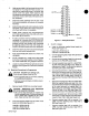
SECTION 1 1-1. SAFETY PRECAUTIONS AND SIGNAL WORDS GENERAL INFORMATION AND SAFETY 1-2. SAFETY ALERT SYMBOL AND SIGNAL WORDS A. General The following safety alert symbol and signal words are throughout this manual to call attention to and iden different levels of hazajd and special instructions.
DESCRIPTION 2-1. The SP-3 is er The SP series is designed to program specific functions of the Syncrowave welding power source. All of the mod els are equipped with Electroslope which provides initial output selection, upslope time control, downslope time which equipped with Electroslope, and a Sequenc provides electronic control of initial output time, upslope and weld time, and downslope and final output time. . equipped with Electroslope; Pulser, the SP-2; and Sequencer, the same as SP-3.
Solder leads Bi and 4 from PLG2 to correspond ing leads from PL1. Slide sleeving back into posi 4. tion after soldering. Insert lead 160 from PLG4 into hole 27 at RC3. Be 20. one coming from remote control recep tacle RC2. Cut lead 11 approximately 6 in. (152 mm) from RC2. coming 8. Tape wiring har C. ness. 1. Locate lead 31 at contactor control switch S4. 2. Connect lead 31 from PLG2 to S4 as (ground) coming from PLG4 to mounting bolts holding circuit board en in place.
1 provided in the front panel but not in the nameplate for mounting the Pulser controls. Lo cate the four prepunched holes in the lower right corner of the front panel. Mark locations onto nameplate by applying pressure from rear with a sharp tool. Punch or drill holes of the same size in the nameplate. Holes 3. are 3 Leadl34 LeadbOl Rotate Pulser controls fully counterclockwise, and install at ers supplied knobs onto shafts zero (0) or minimum. with . 1210 11 100 100 18~0 20100 22 10 ~i.
Lead Top Connect q. 144-(Iong) supplied lead 163 to the terminal S50 where lead 132 maining Lead removed. Connect was end of lead 163 to terminal 9 on re CR56. on For SP-3 Models 4. a. Connect supplied lead 501 to terminal 2 on CR55. Connect remaining end of lead 501 to center terminal of PULSER switch S400. b. Connect supplied lead 81 to terminal remaining end of lead 81 8 CR55. Connect on to the top terminal of S400.
pulser module to the Programmer circuit Connect lead 42 from the 6. threaded mounting board PC500. Connect lead 132 from the pulser module to ter minal 10 on CR56. 7. REMOTE EMERGENCY STOP SWITCH CON 3-3. NECTIONS (Switch Not Supplied) spacer for a WARNING: ELECTRIC SHOCK Do not touch live electrical Shutdown 9. Align supplied PC500 Thread leads 81, 86, and 114 from the pulser module, through the access hole in the bottom of 10.
This switch may be manually operated or may be a fix a-mounted limit switch. If remote downslope initiation ~ desired, obtain switch and 1. Remove proceed Programmer top Route leads from switch 2. left 4. mer rear panel. Remove jumper links 162 on follows: Terminals: cover. through on access left side of Program Reinstall Programmer top 7. Resume operation. 3-6. HAND And SP-2 A DelayedN.C. 5 & 4 Delayed NC.
SECTION 4 Programmer Initial Amperage Switch OPERATOR CONTROLS Upslope Time Control Downslope Final Time Control Control Amperage Electroslope Control Switch Auto-Manual Switch Start Push Button Stop Push. Button Upslope And Weld Amperage Time Downslope And Final Amperage Time Pulser Switch Background Amperage Control % On Time Control Pulses Per Second Control *SMAW/GTAW Switch On SP-1 And SP-2 Modela . TC-046 482 Figure PROGRAMMER SWITCH 4-1. 4-1.
Chart 4-1. Weld Automatic Cycle Timing Operation Using Electronic Timers r J Manual Operation Using Remote Hand Switch (RHS-46) POINT FUNCTION L A Programmer START B Preflow timer in the gins C source be to time. Preflow ends. closes. D power Welding power High frequency available. source AMPERAGE control active. Pulsing ends. button pressed. welding FINAL TB-046 960 M Final amperage time. N Arc extinguished. Postffow timer source begins to time.
20% C. UPSLOPE TIME Control The U PSLOPE TIME control sets the time it takes for the weld output to slope from the setting of the Programmer INITIALAMPERAGE control to the setting of the welding power 50% On Time Peak Amperage AMPERAGE CONTROL. source - Background Amperage Rotating the control clockwise increases time. The scale surrounding the control is calibrated directly in seconds (0 to 10). D.
Rotating the control clockwise increases background amperage. The scale surrounding the BACKGROUND AMPERAGE control is calibrated in percentage and should not be read as an The DOWNSLOPE AND FINAL AMPERAGE TIME control can seconds. When this starts. SMAW/GTAW SWITCH (SP-1 And SP-2 Mod els) (Figure 4~1) SEQUENCER (SP-3 And SP-4 Models) (Fig ure postflow amperage value. 4-8. 4-7. be set for 00.099.
SECTION 5 a WARNING: ELECTRIC SHOCK can kill; MOVING PARTS can cause serious injury; IMPROPER AIR FLOW AND EXPOSURE TO ENVIRONMENT can damage internal parts. 1. Install and connect unit this manual and the ers 2. Do not touch live electrical parts. ANSI Z49.1. 3. Ventilate to keep from gases. If ventilation is inadequate, breathing device. HOT harm breathing fumes cause Connect work clamp to clean, bare metal at c.
Table 5-1.
SHIELDED METAL ARC WELDING 5-3. (SMAW) b. WARNING: Read and follow safety information at beginning of entire Section 5 before a For MANUAL mode: The Start switch must be held closed proceeding. pulsing 1. Install and connect unit IMPORTANT: If an er source ers 2. Manual. according by setting 4. Place the power source position. 6. Wear as 1. necessary. dry insulating gloves and clothing, and wear welding helmet with proper filter lens according to ANSI Z49. 1.
lime Unit Time Down & Arm Stop Pin 60 Hertz Pin 50 Hertz Pin ... I ~ Figure 6-2. 6-1. Changing Timer Operations CIRCUIT BOARD REPLACEMENT PROCE IMPORTANT: DURES with (Figure 6-2) respect All directions, such to the Retain all hardware removed If a circuit board is found to be the following procedure. faulty, replace board using Do not attempt board a replacement part. can A. 2. kill.
Ret. TD-046 484-A Figure 6-3. TROUBLESHOOTING (Table 6-1) a WARNING: ELECTRIC SHOCK 6-2. Circuit Board can kill. Shutdown welding powersource, and discon input power employing lockout/tagging procedures before inspecting or servicing. nect Lockout/tagging procedures consist of padlock ing line disconnect switch in the open position, removing fusesfrom fuse box, or shutting off and red-tagging circuit breaker or other disconnect ing device. Allow can cause severe burns.
Table 6-1 TROUBLE .Troubleshooting CAUSE No weld output. No output from REMEDY welding power source. Turn Programmer source ers off and check welding power output. See welding power Manual for source Own troubleshooting information. . controls Programmer properly. always off or on. im- Check all control settings. . switches. Check all switches and be sure they are fied (see Sections 3-3 thru 3-6). Relay CR56. Replace CR56. Sloper Replace PC500 (see Section 6-2).
SECTION 7 ELECTRICAL DIAGRAMS . RMI EM ERG STOP 3/ 0 148 42 0 501 PLO1 >2 58 I >3 20 >~ . SLOPER CIRCUII BOARD PC500 4 PLC~3 . Circuit Diagram OM-531 Page 18 7-1. Circuit Diagram For SP-1 Models Diagram No.
R MT. EMERG. STOP ~ ~ 50 T 10 11 1213 Circuit Diagram 7-2. Circuit Diagram Diagram No.
37464 AND CLOSE REMOVE FOR REMOTE DOWNSLOPE 648 162 JUMPER OF INITIATION RMT. EMERG. S-TOP 31 64 0 q 77 762 0 p 761 qpSoT REMOVE FOR 57-4 CR51 1~~~ ELECTROSLOPE SP-4 I ~ ONLY~ iNITIAL CR50 2 OFFOI 4,5 I CR S 54 CRSO -~~j.,g~__!__.
ISV. 52 -I-CO T >8 100 >15 44D-9, r.0O.hIO_1N2 Dl-24--.J Li__tlbs_22 1N71 IN2_14_1 j NC2 GRD3 ~ NC-a l____h14-INI SI-3EjI 13-NC ~$314-S2 bla-vu 12-V1 ICsa S2~ 10-sj S4_6 22-6 9-01 D~7 027 9000F L I209EF 690._S Il-NC I1-S~ 1 1 1N49 10-03 9-1N3 0 C Ciruit Diagram No. C-083 530 N) Diagram 7-4.
0 01 Ce) -v CD Co CD N) N) IN;i IN2~I 4.~ ..~JI4INl GRD3~ ci, 41 ~I2Ve NC2 NC4 525 IC5 Ej4D-c- 1 Dr2~j.~ SI-3Cj_-_f 13-NC cscD~4J Is- IN2 Li_his_so bI3-v IC5~ I Il-NC coo-sq 0-NI ~ 041 ~I2-VoEr d( ~i 1N48 pbii-ss i~ 10-03 51N3 Circuit Diagram 7-5. Circuit Diagram For SP-2 Model Sloper Diagram No. C-083 544 Circuit Board PC500 .
. 16 ] V2-4 C 16- 1N2 IN 21 C ]15-DZ C-2 ]14-S2 GRD.-3t ]13- Vi NC-4C 1C52 GRD.-5C 0 S4-6 C 04-1 C C., 1N4-8 C o~_j -~ ~11-S3 02-6 C 310-03 V27C 1C51 111 ~!ft - NC 310-Si 19Di 1 8VF~r Circuit Diagram No. C-049 834-A 19IN3 -D Di CD C., Diagram 7 7-6.
16 6 7 -I- ISV E~ 13 V~ Circuit Diagram . 7-7. Circuit Diagram For SP-4 Model Sloper Circuit Board PC500 Diagram No.
N.~ 1 K4. >506 >502 J~2 3)503 L ~. a> M .~. 5 > 86 505 N ~ 6> 774 P ~ 7> 506 BASE EM JTTER~,~3,COLLECTOR Q400&Q40l Circuit Diagram 7-8. Circuit Diagram Diagram No.
SECTION 8 PARTS LIST . 26 29~ 28-~ TD-046 484-A Figure 8-1. Main Assembly Quantity Item Dia. No. Mkgs. Model Part No. Description Figure 1 +008 872 1 ++052 302 134 327 004 214 5 S51 S51 S50 S50 PB5O PB51 6 CR5O-53,55 000 174 6 000 174 7 CR5O-53 CR54 7 CR54,55 039 498 2 2 3 3 4 OM-531 Page 26 011 609 052 769 052 769 011 611 021 105 021 106 000 770 8-1.
Quantity Model I Item )No. Dia. Mkgs. Part No. Description Figure 8 CR56 049 181 8 CR56 SR3 049 180 035 704 9 605 670 10 073 344 11 50T 038 772 11 50T 038 832 601 219 12 13 C50,51 031 670 8-1. Main SP-1 1 BLOCK, term 20A 9P LINK, jumper term block 20A CAPACITOR, cer .
C-ill 316 Figure 8-2.
13 Quantity Dia. Mkqs. Model Part Description Np. sP-i 05 0 ~. - Figure 8-2. Circuit Card (Fig 8-1 Item A50 035 845 A51,52 008971 A51-55 008 971 C50,51 C52,53 C54,55 000 859 C56 031 628 C57,58,69,76 C57,58,69 C57,58,76 053 992 C59 028 288 CAPACITOR, cer .OOiuf 1000VDC CAPACITOR, elctlt 8uf 25VDC 053 991 CAPACITOR, 053 991 003 530 CAPACITOR, cer .O5uf 500VDC CAPACITOR, elctlt 8uf 25VDC CAPACITOR, cer .O5uf 500VDC CAPACITOR, cer .O2uf 500VDC CAPACITOR, cer .
Quantity Model Dia. M kgs. Part No.
Quantity -Model Item No. Dia. Mkgs. Part No.
. I 7
FORM: OM-531C May 11, 1992 ERRATA SHEET After this manual to data was appearing printed, AMENDMENT TO SECTION 4 Amend the last refinements in equipment design occurred. This sheet lists exceptions later in this manual. OPERATOR CONTROLS paragraph of Section 4-6D. PULSER (SP-2 And SP-4 Models): Background Amperage Control Rotating the control clockwise increases background amperage.