BIC-II BUFFERED INTERFACE CONVERTER Instruction Manual PL-371 January 1996 33453710 Rev 3.
TABLE OF CONTENTS TITLE PAGE # GENERAL INFORMATION About This Manual 1-1 About The BIC II 1-1 Features 1-3 SPECIFICATIONS BIC II 2-1 Cabling 2-2 INSTALLATION BIC-II 3-1 Interconnection 3-1 Internal Checks 3-1 Hardware Set Up 4-1 START UP Host/Millbus Baud Rate 4-1 Self Test 4-1 BIC-II I.D.
BIC PROTOCOL Simplex Convention 7-1 Data Field Descriptions 7-2 Software Set Up 7-2 BIC-II Messages 7-3 Product Messages 7-6 BIC-II PROTOCOL Convention Simplex Convention 8-1 Duplex Convention 8-1 Messages 8-2 Data Field Descriptions 8-2 Software Set Up 8-6 BIC-II Messages 8-6 Product Messages 8 - 10 MODBUS PROTOCOL General 9-1 BIC-II Registers 9-1 BIC-II General Registers 9-2 BIC-II Product Registers 9-4 AiRanger XPL Registers 9-5 AiRanger DPL Registers 9-7 AiRanger IV R
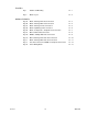
FIGURES Fig. 1 Outline and Mounting 12 - 1 Fig. 2 BIC-II Layout 12 - 2 Fig. 3A BIC-II / AiRanger XPL Interconnection 12 - 3 Fig. 3B BIC-II / AiRanger DPL Interconnection 12 - 4 Fig. 3C BIC-II / AiRanger IV Interconnection 12 - 5 Fig. 3D BIC-II LiquidRanger Interconnection 12 - 6 Fig. 3E BIC-II / CompuScale / CompuFlo Interconnection 12 - 7 Fig. 3F BIC-II / OCM-II Interconnection 12 - 8 Fig. 3G MillBus / Multiple BIC-II Interconnection 12 - 9 Fig.
GENERAL INFORMATION ABOUT THIS MANUAL It is essential that this instruction manual be referred to during the installation and start up of the Milltronics BIC-II. The intent of this manual is to give the user the required information for installation, start up and application of the BIC-II. If the optional MillView software program is to be used (refer to the associated instruction manual), then the customer need only concern himself with the Installation and Start Up sections.
Typical BIC-II Communication Network Compuscale / CompuFlo Integrator LiquidRanger AiRanger DPL AiRanger XPL Products AiRanger IV OCM II CVCC Interface BIC-II Host OR PLC Computer PL-371 1–2
FEATURES ✓ The BIC-II MillBus substantially reduces cable requirements when communication with several Milltronics products is required. ✓ Auto Polarity Detection eliminates the need to observe communication signal polarities when interconnecting the BIC-II with Milltronics products. ✓ A BIC-II self test is automatically performed upon power up. Should a fault be indicated, more extensive tests are available to simplify troubleshooting requirements.
SPECIFICATIONS BIC-II » 100/115/200/230 V ± 15% jumper selectable Power : » 50/60 Hz, 50 VA Power Fuse : Products : » 2/10 amp MDL Slo-Blo » BIC mode : » 1 of : » » » » » » » BIC-II mode : » any combination to a maximum of 6 products/BIC-II (refer to Functional \ Product Load Factor) : » » » » » » » » » AiRanger XPL AiRanger DPL AiRanger IV LiquidRanger AiRanger XPL Plus AiRanger DPL Plus AiRanger XPL Plus AiRanger DPL Plus AiRanger XPL AiRanger DPL AiRanger IV LiquidRanger CompuScale IIA CompuF
Protocol : » Host / BIC II : » ASCII messages, 7 bit word, even parity, one stop bit. » ASCII messages, 8 bit word, no parity, one stop bit.
INSTALLATION BIC-II The BIC-II should be mounted in an area that will allow operation within the specified operating temperature range and that is suitable for NEMA 4 enclosures and polycarbonate material. The front cover should be accessible and have sufficient room to swing open. Refer to Fig. 1 - Outline and Mounting Detail. It is advisable to keep the BIC-II away from high voltage or current runs, SCR control drives and RF interference.
START UP HARDWARE SET UP HOST / MILLBUS BAUD RATE Determine the serial communication baud rate of the host computer or PLC and open the SW 1 contact (1-5) corresponding to the desired baud rate. (Refer to Functional/Product Load Factor.) Close all other baud rate contacts. HOST / MILLBUS WORD LENGTH Determine the word length of each character of the host serial communication and set SW1 contact 6 accordingly. 7 bit word, even parity, one stop bit or 8 bit word no parity, one stop bit.
OPERATING MODE board A SW 2 SPARE 8 e.g. BIC-II BIC / BIC-II 7 e.g. BIC-II 6 › SW 2 - 6 : set contact to correspond to the desired protocol. › BIC : may be used when replacing a BIC with a BIC-II (refer to Functional \ Operating Modes \ BIC) › BIC-II : normally selected for most new applications BIC-II / MOD › SW 2 - 8 : set contact to correspond to the desired protocol. › BIC-II: as determined by SW 2-6 › MOD: Selected when the host device utilizes Modbus ASCII protocol.
FUNCTIONAL SERIAL COMMUNICATION In general, Milltronics products designed for serial communication transmit data over a bipolar current loop. This format allows for communication loop lengths of 3000 m (10,000 ft) as opposed to limited runs of 15 m (50 ft) as afforded by RS-232 or RS-422. Some Milltronics products use the RS-232 format for direct connection to a computer.
MODBUS MODE This mode permits the BIC-II to operate as a Modbus ASCII slave device. By utilizing register mapping similar to that used by most PLC’s, the BIC-II is easily configured to communicate with up to 6 Milltronics products. PRODUCT LOAD FACTOR Product Load Factor, is a value used to represent the amount of the BIC-II’s communication capacity utilized by a connected Milltronics product.
e.g. Communication with the following products is desired with the BIC-II Host/Millbus set to 9600. » 1 AiRanger XPL (EPROM software 2.2) » 1 AiRanger DPL (EPROM software 11.0) » 1 Liquid Ranger (9600 baud) » 1 AiRanger IV (9600 baud) Product Load Factor = 25 (XPL) + 30 (DPL) + 30 (LiquidRanger) + 30 (AiRanger IV) = 115 In this case 2 BIC-II’s would be required.
APPLICATIONS The following examples illustrate the most common applications to which the BIC-II may be applied. Refer to the example which best resembles the intended BIC-II application. SINGLE BIC-II - EXAMPLE An IBM compatible computer is to display the material inventory on hand, contained in 8 vessels monitored by a Milltronics level measurement product (e.g. AiRanger XPL). Refer to Figures for BIC-II general mounting and interconnection instructions.
BIC REPLACEMENT - EXAMPLE A BIC utilized for communication between an AiRanger DPL and a host device is to be replaced by a BIC-II. Disconnect the BIC and connect the AiRanger DPL communication cable to the BIC-II \ PORT1. Ensure the AiRanger DPL is operating at 4800 baud. Refer to the associated instruction manual. Connect the appropriate BIC-II, RS-232 or RS-422 port to the host device. Refer to Start Up\Hardware Set Up for BIC-II, board A, switch SW1 and SW2 contact settings.
MULTIPLE BIC-II’s - EXAMPLE A communication network is to be established which will require a PLC to communicate with 2 AiRanger IV’s set to 9600 baud and 4 AiRanger DPL’s with software revision number 2.3 EPROM’s. The AiRanger IV’s are located at opposite ends of the plant, and the AiRanger DPL’s are distributed in between. The PLC will be located in the control room 400 m away. The BIC-II Host/Millbus communications is to be at 9600 baud.
BIC PROTOCOL This is the protocol utilized when a BIC-II is operating in the BIC mode, as an interface between a host device and a Milltronics product utilizing simplex convention. The BIC mode is intended for use when a BIC-II is replacing a previous generation BIC in an existing installation. For new installations, use the BIC-II or Modbus operating modes (FUNCTIONAL \ Operating Modes) and refer to the corresponding protocol section of this instruction manual. When replacing an existing BIC... 1. 2. 3. 4.
DATA FIELD DESCRIPTIONS For instruction purposes, messages are divided into a number of data fields. By identifying data fields, each section of the message is more easily defined. The following data fields and corresponding ASCII character values are utilized in BIC-II messages. SOM (Start Of Message) This field contains the Host/BIC-II start of message character. ASCII character = STX (normally generated by simultaneously pressing Ctrl B on a keyboard) BIC-II I.D.
BIC-II MESSAGES The following messages may be transmitted from the host to instruct the BIC-II to perform the operation specified. The ASCII characters have been provided as an example only. RAM TABLE REQUEST This message is transmitted from the host to retrieve the message stored in the BIC-II RAM table. Data Field ASCII Character Example Description SOM BIC-II I.D. MT POINT EOM STX 1 20 001 CR start of message BIC-II #1 (e.g.) (range = 1 to 8) retrieve data from the RAM table point #1 (e.g.
RESET Reset may be used to reset the BIC-II to the factory BIC mode software setup. When a Reset message is transmitted from the host, the BIC-II resets: » » » Delimiters to off. Format to normal. Product Mode to AiRanger Series level product. A Reset is not required after a BIC-II power interruption. Transmit the following message from the host to the BIC-II to activate a Reset. Data Field ASCII Character Example Description SOM BIC-II I.D. MT EOM STX 1 26 CR start of message BIC-II #1 (e.g.
FORMAT This message may be transmitted from the host to instruct the BIC-II to alter the format of the product message. (Refer to Product Messages). Format is automatically reset to "normal" during a BIC-II power up. The alternate Format (when activated) may be manually reset to "normal" using the RESET message. The format command should not be used if an AiRanger XPL is connected to the BIC-II. Transmit the following message from the host to the BIC-II to select Alternate Format.
PRODUCT MESSAGES Product Messages refers to messages which may be received by the host from the BIC-II in response to a RAM Table Request or FIFO Buffer Request message. The AiRanger IV and LiquidRanger are capable of receiving messages. These messages are transmitted from the host to the BIC-II, which in turn relays the message to the product. These messages are referred to as Product Messages as well.
AIRANGER XPL When the BIC-II is in the AiRanger mode (factory setting), the AiRanger XPL, XPL Plus or DPL Plus Measurement message (MT00) will be as follows: PL-371 Data Field ASCII Character Example Description SOM BIC-II I.D. MT POINT READING STATUS A STATUS B STATUS C STX 1 00 001 2758 F 0 0 STATUS D STATUS E 0 0 STATUS F 0 CONFIDENCE ANALOG EOM 99 000 CR start of message BIC-II #1 (e.g.) (range = 1 to 8) Message Type 00 (e.g.) (Product Data) point #1 (e.g.
ALTERNATE FORMAT When the Format message is transmitted from the host to the BIC-II, an AiRanger IV or AiRanger DPL measurement (MT00) is altered by the BIC-II as follows (until a Reset occurs). Data Field ASCII Example Character Description SOM BIC-II I.D. MT POINT READING IN SERVICE NEW READING ALARM ACKN. STATUS STX 1 00 001 2758 1 0 1 PrFSHHFI EOM CR start of message BIC-II #1 (e.g.) (range = 1 to 8) Message Type 00 (e.g.) (Product Data) point #1 (e.g.
BIC-II PROTOCOL This is the protocol utilized when the BIC-II is operating in the BIC-II mode, as an interface between the host device and Milltronics products utilizing simplex and/or duplex convention. CONVENTION SIMPLEX CONVENTION Simplex convention is the unsolicited transmission of messages from the product to the BIC-II.
MESSAGES The following diagrams illustrate messages that can be used when communicating under specific convention and to specific products. BIC-II Message Request Product Message (unsolicited) Product Message Response Used to retrieve a product message stored in the BIC-II. SIMPLEX CONVENTION Product Message * Air IV & LiquidRanger ONLY Used to send an instruction to the product. No response retrieved.
SOM (Start Of Message) This field contains the Host/BIC-II start of message character. ASCII character = STX (normally generated by simultaneously pressing Ctrl B on a keyboard) BIC-II I.D. This field identifies which BIC-II the message is associated with. Refer to Start Up \ Hardware Set Up \ BIC-II I.D.#. ASCII values = 01 to 31 PORT Identifies which BIC-II product port the message is associated with.
MSG (Product Message) Contains the message received from (or in some cases, transmitted to) the product connected to the BIC-II product port. The type and sequence of the data fields will be dependent upon the product type and the message type. Refer to the appropriate product instruction manual for the message structure. MT (Message Type) Identifies the type of message received from (or in some cases, transmitted to) the product connected to the BIC-II product port.
STOP Identifies the number of stop bits that will be utilized in each byte of the messages received from (or transmitted to) the product connected to the BIC-II product port. ASCII values = 1.0 1.5 2.0 STATUS Indicates the results of the latest system test. ASCII characters 000 indicate a successful system test. ASCII values = 000 to 255 MASK Resets the Status field fault indication. ASCII characters 000 reset the Status indication to 000. ASCII values = 000 to 255.
SOFTWARE SET UP Each product port must be set up to identify the structure and sequence of the messages that will be received from the Milltronics product connected. This is achieved by transmitting the appropriate BIC-II Port Initialization command message, B1 or B2, (prior to any data request messages) from the host to the BIC-II. This information is stored in the BIC-II EEPROM and therefore will not be affected by power interruptions.
DUPLEX PORT INITIALIZATION This message prepares a BIC-II port to communicate with a product utilizing duplex convention. Data Field SOM BIC-II I.D. COMMAND PORT BAUD PARITY DATA STOP som eom EOM ASCII Character Example Description STX 01 B2 1 09600 N 8 1.
The response received will consist of the following data fields : SOM ➟ BIC-II I.D. ➟ PORT ➟ MSG ➟ EOM The contents of the MSG field will be equal to the message transmitted from the product to the BIC-II less the products ’start of message’ and ’end of message’ characters. Refer to the product instruction manual for message types and structures. Retrieve data from the RAM table until data for all points has been retrieved.
SELF TEST This message instructs the BIC-II to perform an on-line self test and return the results. Data Field ASCII Character SOM BIC-II I.D. COMMAND EOM Example Description STX 01 B6 CR start of message BIC-II #1 perform a self test end of message The response to the host from the BIC-II will indicate the results of the self test and will consist of the following data fields: SOM ➟ BIC-II I.D. ➟ COMMAND ➟ STATUS ➟ EOM If the self test was successful, the status field characters will be 000.
Performing a new ‘Self Test’ after an ‘Error Reset’ is recommended. If the cause of any persistent error cannot be determined contact Milltronics or your distributor. PROGRAM TIP PRODUCT MESSAGES Product messages transmitted from the Host to the BIC-II must be in the following format : SOM ➟ BIC-II I.D. ➟ PORT ➟ MSG ➟ EOM The BIC-II removes the ‘SOM’, ‘BIC-II I.D.’, ‘PORT’ and ‘EOM’, data fields and then adds the product ‘som’ and ‘eom’ data fields.
MODBUS PROTOCOL GENERAL In recent years, Modbus has become an industry standard communications protocol for PLC’s (Programmable Logic Controllers) and DCS’s (Distributed Control Systems). The BIC-II supports Modbus ASCII (non RTU) communications.
BIC-II GENERAL REGISTERS Self Test The BIC-II Self Test is an on-line self diagnostic feature which checks and reports on the health of the BIC-II hardware. Activate the BIC-II Self Test following: power up, write/read Port Initialization conflict, erroneous data, and as frequently as otherwise desired. Some MMI software packages may include provisions for diagnostics utilizing Modbus Function 8, codes 02 and 10. These operations are supported by the BIC-II.
Port Initialization A Port Initialization prepares the BIC-II to communicate with a Milltronics product. Write a Port Initialization message for each BIC-II product port used, before attempting to Read/Write product data. The product port will remain initialized indefinitely, however it is recommended, the Port Initialization registers be read and verified following: power up, power resumption, or erroneous data. If the product (or product baud rate) is changed, write a new Port Initialization.
Hold Condition Read the HOLD CONDITION register frequently during normal operation. A product HOLD occurs whenever a simplex convention product is taken out of the RUN mode. The HOLD status is updated when the associated product is returned to the RUN mode.
REGISTERS When a Port Initialization configures a BIC-II product port to suit an AiRanger XPL, XPL Plus or DPL Plus, the product data registers (read only) are assigned as follows. Status Registers AiRanger XPL, XPL Plus and DPL Plus Status registers indicate the general health of the Milltronics product (and process monitored). Port 1 Status registers range from 40001 to 40010, corresponding to the AiRanger XPL and XPL Plus points of measure 1 to 10 respectively.
Air Temperature Registers AiRanger XPL, XPL Plus and DPL Plus Air Temperature registers contain a value derived from the air temperature measurement for the associated point of measure. Subtract 100 from the decimal equivalent of this value for degrees Celcius. Port 1 Air Temperature registers range from 40031 to 40040, corresponding to points of measure 1 to 10 respectively. ( DPL Plus Port 1 Air temperature registers range from 40010 to 40012 ).
AIRANGER DPL REGISTERS When a Port Initialization configures a BIC-II product port to suit an AiRanger DPL, the product data registers (read only) are assigned as follows. Status Registers AiRanger DPL Status registers indicate the general health of the Milltronics product (and process monitored). Port 1 Status registers range from 40001 to 40006, corresponding to the AiRanger DPL points of measure.
Reading Registers AiRanger DPL Reading registers contain the measurement display value. Two registers are used for the reading associated with each point of measure. Port 1 Reading registers 40007 and 40008 apply to point 1, 40009 and 40010 to point 2, 40011 and 40012 to point 3. Check the first register for a value of 56,797 ($DDDD) (point out of service) or 61,166 ($EEEE) (display overflow).
AIRANGER IV READ ONLY REGISTERS When a Port Initialization configures a BIC-II product port to suit an AiRanger IV, the product data registers are assigned as follows. Status Registers AiRanger IV Status registers (read only) indicate the general health of the Milltronics product (and process monitored). Port 1 Status registers range from 40001 to 40120, corresponding to the AiRanger IV points of measure 1 to 60. Registers 40001 and 40002 apply to point 1, 40003 and 40004 to point 2, etc.
Reading Registers AiRanger IV Reading registers (read only) contain the measurement display value. Two registers are used for the reading associated with each point. Port 1 Reading registers range from 40121 to 40240, corresponding to the AiRanger IV points of measure. Registers 40121 and 40122 apply to point 1, 40123 and 40124 to point 2, etc. Check the first register for a value of 56,797 ($DDDD) (point out of service) or 61,166 ($EEEE) (display overflow).
LIQUIDRANGER READ ONLY REGISTERS When a Port Initialization configures a BIC-II product port to suit a LiquidRanger, the product data registers are assigned as follows. Status Registers LiquidRanger Status registers (read only) indicate the general health of the Milltronics product (and process monitored). Port 1 Status registers range from 40001 to 40120, corresponding to the AiRanger IV points of measure 1 to 60. Registers 40001 and 40002 apply to point 1, 40003 and 40004 to point 2, etc.
Reading Registers LiquidRanger Reading registers (read only) contain the measurement display value. Two registers are used for the reading associated with each point. Port 1 Reading registers range from 40121 to 40240, corresponding to the AiRanger IV points of measure. Registers 40121 and 40122 apply to point 1, 40123 and 40124 to point 2, etc. Check the first register for a value of 56,797 ($DDDD) (point out of service) or 61,166 ($EEEE) (display overflow).
COMPUX WRITE ONLY REGISTERS When a Port Initialization configures a BIC-II product port to suit a CompuScale or CompuFlo series integrator, several write only registers are established. Write the integrator I.D. number to the appropriate register. NAME NUMBER DESCRIPTION MT50 MT51* MT52* MT53 40001 40002 40003 40004 request Port 1 Rate data. request Port 1 Load data. request Port 1 Speed data. request Port 1 Total data. * applies to CompuScale series integrators only.
TROUBLESHOOTING SELF TEST The BIC-II is capable of performing two levels of automatic self diagnostic tests upon initial power up; Normal, and Test. The on board LED indicators will illuminate in a specific sequence during these tests.
TEST The BIC-II performs more extensive circuitry tests and then awaits the operator to perform a DIP switch and LED test. Set the BIC-II, board A, switch SW1 contact 8 to the TST position. Flip the BIC-II, board B, POWER switch to ON.
BIC-II TEST DISK The BIC-II Test Disk (copyright Milltronics 1991) communication test program operates under MS-DOS. This program tests communication between an IBM PC compatible personal computer, the BIC-II and a Milltronics product, using simplex convention. The BIC-II Test Disk is enclosed with the BIC-II in its shipping box.
BIC-II MODBUS PROTOCOL REGISTER MAP PORT REGISTER XPL DPL AIR4 LIQUID COMPUX DPL Plus XPL Plus 1 * STATUS * READING * CONFIDENCE * ANALOG * AIR TEMP * LIQUID TEMP * PERCENT MT10 MT11 MT12 MT13 MT50 MT51 MT52 MT53 * UNITS * HOLD PORT INITIALIZATION SELF TEST 40001-40010 40011-40030 ------40031-40040 ---40041-40060 ---------------------------46001 47001 48001 40001-40006 40007-40012 40013-4001 40016-40018 ------------------------------------46001 47001 48001 40001-40120 40121-40240 40241-40300 403
BIC-II MODBUS PROTOCOL REGISTER MAP PORT REGISTER XPL DPL AIR4 LIQUID COMPUX DPL Plus XPL PLus 4 * STATUS * READING * CONFIDENCE * ANALOG * AIR TEMP * LIQUID TEMP * PERCENT MT10 MT11 MT12 MT13 MT50 MT51 MT52 MT53 * UNITS * HOLD PORT INITIALIZATION SELF TEST 43001-43010 43011-43030 ------43031-43040 ---43041-43060 ---------------------------46001 47004 48001 43001-43006 43007-43012 43013-43015 43016-43018 ------------------------------------46001 47004 48001 43001-43120 43121-43240 43241-43300 43
PLC REQUIREMENTS As Programmable Logic Controllers continue to revolutionize the process control industry, new and innovative ideas become reality very quickly. The BIC-II was designed to be compatible with PLC’s of the future, as well as those which have already been commisioned a number of years ago. To this end, the BIC-II provides communication protocol options which should suit all application requirements. One important consideration is that the BIC-II is strictly a slave device.
ASCII / HEXADECIMAL / BINARY CONVERSION CHART ASCII CHARACTER ASCII HEXADECIMAL ASCII BINARY TRUE HEXADECIMAL TRUE BINARY STX LF CR .
OUTLINE AND MOUNTING 16 mm (0.6") 209 mm (8.2") lid screws ( 6 places ) 172 mm (6.8") 91 mm (3.6") 285 mm (11.2") 267 mm (10.5") lid, clear polycarbonate suitable location for conduit entrances (water tight conduit hubs should be used to maintain the enclosure rating) mounting holes (accessed under lid) 4.3 mm (0.17") dia, 4 places CSA enclosure 4 polycarbonate customer mounting screw Milltronics recommends using a punch for making holes in enclosure. FIG.
BIC-II LAYOUT FIG.
WIRING FORMATS BIC-II / AiRanger XPL Interconnection BIC-II to other products as required communication loop AiRanger XPL #1 1. BIC-II, ports 1-6, Rx input is non-polarized. 2. Refer to instruction manual PL-336 for wiring of AiRanger XPL. Check that communication parameter (P-54) is ON. 3. BIC-II interconnecting cable shield should be connected at AiRanger XPL only. Insulate shields at junctions to prevent inadvertent grounding. Use Belden cable 8760, 1 pair shielded / twisted, 18 AWG or equivalent.
WIRING FORMATS (cont’d) BIC-II / AiRanger DPL Interconnection BIC-II PORT 1 Rx + Board B TB1 Tx + PORT 2 Rx + Tx + PORT 3 Rx + Tx + PORT 4 Rx + PORT 5 Tx Rx + + Tx + PORT6 Rx + Tx + 1 2 3 4 5 6 7 8 9 101112131415161718192021222324252627282930 to other products as required communication loop MILLIAMPS S TEMP.
WIRING FORMATS (cont’d) BIC-II / AiRanger IV Interconnection BIC-II AiRanger IV #1 Terminal Board TB3 1 2 3 4 5 6 7 8 9 10 11 12 SHLD RC1 TB1 POWER + 1 2 H I TRANSMIT + 3 G A 4 H + 5 L RECEIVE 6 A R GR 7 M + 8 mA L S OUTPUT 9 O BLK 10 W TEMP. WHT 11 SENSOR GR 12 HOT RC2 TB2 PORT 1 Rx + Board B TB1 Tx PORT 2 Rx + + Tx PORT 3 Rx + + Tx PORT 4 Rx + + Tx PORT 5 Rx + + PORT6 Tx Rx + + Tx + 1 2 3 4 5 6 7 8 9 101112131415161718192021222324252627282930 to other products as required 1.
WIRING FORMATS (cont’d) BIC-II / LiquidRanger Interconnection LiquidRanger #1 PS - 20 TB1 1 2 HIGH 3 4 LOW 5 6 7 RC1 8 RECEIVE 9 SHIELD 10 11 12 SHIELD 13 14 15 SHIELD TRANSMIT 16 17 + + BIC-II PORT 1 Rx + Board B TB1 Tx PORT 2 Rx + + Tx PORT 3 Rx + + PORT 4 Tx Rx + + Tx PORT 5 Rx + + Tx + PORT6 Rx + Tx + 1 2 3 4 5 6 7 8 9 101112131415161718192021222324252627282930 + + to other products as required 18 SHIELD 19 4-20 mA 20 OUTPUT 21 SHIELD 22 24 V DC 23 + + 1.
WIRING FORMATS (cont’d) BIC-II // CompuScale IIA / CompuFlo Interconnection CompuScale IIA / CompuFlo 1TB BIC-II PORT 1 PORT 2 PORT 3 PORT 4 PORT 5 PORT6 +Rx- +Tx- +Rx- +Tx- +Rx- +Tx- +Rx- +Tx- +Rx- +Tx- +Rx- +TxBoard B TB1 1 2 3 4 5 6 7 8 9 10 11 12 13 14 15 16 17 18 19 20 21 22 23 24 25 26 27 28 29 30 to other products as required 1 2 3 4 5 6 7 8 9 10 11 12 13 14 15 16 17 18 19 20 21 22 23 24 25 26 27 28 29 30 31 32 33 34 - RATE + 4 - 20 mA - CONTLR + 4 - 20 mA - SIG. A - SIG. B + SIG. COM.
WIRING FORMATS (cont’d) BIC-II / OCM-II Interconnection OCM II TRANS- TEMP. DUCER.
WIRING FORMATS (cont’d) MillBus / Multiple BIC-II Interconnection MILLBUS IN + - Board B TB2 RS-232 P C O C OUT 12 I O U O + - V N M T M C O IN M + - 1 2 3 4 5 6 7 8 9 10 11 12 13 14 15 16 17 18 MILLBUS IN + - Board B TB2 RS-422 P 5 OUT V + - RS-232 P C O C OUT 12 I O U O + - V N M T M C O IN M + - BIC-II #1 RS-422 P 5 OUT V + - 1 2 3 4 5 6 7 8 9 10 11 12 13 14 15 16 17 18 BIC-II #2 Belden 8760, 1200 m (4000 ft) maximum run from BIC-II #1 to last BIC-II MILLBUS IN + - Board B TB2 RS-232
WIRING FORMATS (cont’d) BIC-II / AiRanger XPL Plus Interconnection BIC-II to other products as required communication loop AiRanger XPL Plus #1 (Board B) 1. BIC-II, ports 1-6, Rx input is non-polarized. 2. Refer to instruction manual PL-400 for wiring of AiRanger XPL Plus. Check that Peripheral Communications (P-740) is set for "normal". 3. BIC-II interconnecting cable shield should be connected at AiRanger XPL Plus only. Insulate shields at junctions to prevent inadvertent grounding.
WIRING FORMATS (cont’d) BIC-II / AiRanger DPL Plus Interconnection BIC-II to other products as required communication loop AiRanger DPL Plus #1 (Board B) 1. BIC-II, ports 1-6, Rx input is non-polarized. 2. Refer to instruction manual PL-421 for wiring of AiRanger DPL Plus. Check that Peripheral Communications (P-740) is set for "normal". 3. BIC-II interconnecting cable shield should be connected at AiRanger DPL Plus only. Insulate shields at junctions to prevent inadvertent grounding.
WIRING FORMATS (cont’d) Host Interconnection RS 422 Format RS 232 Format Interface BIC-II Interface BIC-II OR Belden 9552, max run 15 m (50 ft) Belden 9552, max run 15 m (50 ft) to customer’s host device * to customer’s host device The interface BIC-II must have the indicated jumpers removed. Refer to MillBus / Multiple BIC-II Interconnection.
WIRING FORMATS (cont’d) Power Wiring Detail isolated common OR chassis ground Ensure jumper J2 connection matches the power to be supplied at TB3 - 2 / 3 Power connection 100 / 115 / 200 / 230 V AC 1. All wiring must be done in conjunction with approved conduit, boxes and fittings and to procedures in accordance with all governing regulations. 2. Select either isolated common or chassis ground J1 jumper position. The isolated common position should be selected if ground loop problems are suspected.