
Instruction manual


OPERATING MODE
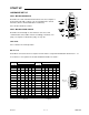
› SW 2 - 6 : set contact to correspond to the desired protocol.
› BIC : may be used when replacing a BIC with a BIC-II
(refer to Functional \ Operating Modes \ BIC)
› BIC-II : normally selected for most new applications
› SW 2 - 8 : set contact to correspond to the desired protocol.
› BIC-II: as determined by SW 2-6
› MOD: Selected when the host device utilizes Modbus ASCII
protocol. This setting disables SW 2-6.
PRODUCT LOAD FACTOR
If more than one Milltronics product is to be connected to a BIC-II, refer to Functional \ Product Load Factor
before proceeding.
SOFTWARE SET UP
Some BIC-II set up requirements are received from the host computer or PLC.
If a Milltronics MillView display system is utilized, refer to the associated instruction manual.
If an alternate software package or PLC is to be utilized, refer to Protocol.
POWER UP
Flip the power switch, SW1, on board B to the ON position. The BIC-II will automatically perform a self test
for about 15 seconds prior to normal operation.
If the TST self test was selected during the hardware set up
or if any BIC-II LED remains (RED) refer to Troubleshooting.
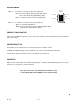
■
e.g. BIC-II
e.g. BIC-II
board A
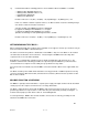
SW 2
BIC-II / MOD
678
SPARE
BIC / BIC-II
PL-371 4 – 2