Instruction Manual June 2002 XPS/XCTTRANSDUCERS XPS/XCT SERIESTRANSDUCERS
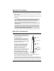
Safety Guidelines Warning notices must be observed to ensure personal safety as well as that of others, and to protect the product and the connected equipment. These warning notices are accompanied by a clarification of the level of caution to be observed. Qualified Personnel This device/system may only be set up and operated in conjunction with this manual. Qualified personnel are only authorized to install and operate this equipment in accordance with established safety practices and standards.
General Information Refer to this manual for proper installation, operation, and maintenance of the XPS/XCT Series Transducers. Special attention must be paid to warnings and notes highlighted from the rest of the text by grey boxes. WARNING means that failure to observe the necessary precautions can result in death, serious injury, and/or considerable material damage. Note means important information about the product or that part of the operating manual.
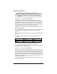
General Guidelines WARNING: Materials of construction are chosen based on their chemical compatibility (or inertness) for general purposes. For exposure to specific environments, check with chemical compatibility charts before installing. XPS/XCT Series - Certificate SIRA 99ATEX5153X This equipment may be used in hazardous areas associated with all gases with temperature classes T1, T2, T3 and T4 for the XPS series (XPS-10, XPS-15, XPS-30 and XPS-40) and T1, T2 and T3 for the XCT series (XCT-8 and XCT-12).
These devices should only be supplied from a circuit containing a suitably rated fuse that has a breaking capacity of 4000A. This fuse is included in Siemens Milltronics transceivers. Repair of the equipment shall be carried out in accordance with the applicable code of practice and Installation Instructions.
Specifications Model : Measurement Range, m (ft): XPS - 10 XPS - 15 XPS - 30 XPS - 40 XCT - 8 XCT - 12 0.3 - 10 0.3 - 15 0.6 - 30 0.9 - 40 0.6 - 8 0.
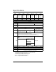
Outline and Dimensions B B radiating face A C standard optional bonded flange refer to associated instructions D F C optional split flange refer to associated instructions E optional submergence shield refer to associated instructions Model Dimension XPS 10 XPS - 15 A 86 mm (3.4") 119 mm (4.7") 173 mm (6.8") 206 mm (8.1") 86 mm (3.4") XPS - 30 XPS - 40 XCT - 8 XCT - 12 119 mm (4.7") B 122 mm (4.8") 132 mm (5.2") 198 mm (7.8") 229 mm (9.0") 122 mm (4.8") 132 mm (5.
Mounting Dos and Don’ts Special handling precautions must be taken to protect the face of the transducer from any damage. Mount the transducer so that it is above the maximum material level by at least the blanking value. Refer to the associated transceiver manual. On liquid applications, the transducer must be mounted so that the axis of transmission is perpendicular to the liquid surface. On solids applications, a Milltronics Easy Aimer should be used to facilitate aiming of the transducer.
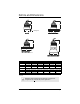
Mounting - Liquid Applications Flexible Conduit Bracket flexible conduit steel channel coupling safety chain transducer Flexible conduit mounted transducer should not be subjected to wind, vibration or jarring. Submersible Plywood rigid metal conduit coupling safety chain submergence shield Submersible transducer, used in applications where flooding is possible. 7ML19981AK01 Plywood mounting provides excellent isolation, but must be rigid enough to avoid flexing if subjected to loading.
Mounting - Liquid Applications (cont’d) Blind Flange nipple welded to blind flange coupling Flange, gasket and hardware supplied by customer. Refer to Liquid Applications - Standpipes Note: Tighten the flange bolts evenly in order to ensure a good seal between the mating flanges. Caution: Overtightening can cause performance degradation. Flanged coupling factory flanged transducer bolt gasket customer flange, flat face only nut Customer flanged standpipe.
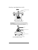
Interconnection Milltronics transceiver (typical) b l k / h o t Direct Connection w h t / s h l d For EnviroRanger ERS 500 only, connect all three wires separately. blk wht drain / shield 2 Wire Extension wht For EnviroRanger ERS 500 only, connect all three wires separately. blk junction box drain / shield extend cable using 18 AWG shielded / twisted pair Coaxial Extension When connecting to an EnviroRanger 500, do NOT use coaxial cable, use a 2-wire extension as illustrated above.
Dos and Don’ts Installation shall only be performed by qualified personnel and in accordance with local governing regulations. Do not route cable openly. For optimum isolation against electrical noise, run cable separately in a grounded metal conduit. Seal all thread connections to prevent ingress of moisture. Do not run cable near high voltage or current runs, contactors and SCR control drives. Note: For pressure tight applications, install transducers hand tight plus ½ turn to 1½ turns.
Applications The transducer is to be used only in the manner outlined in this instruction manual. Normally, the transducer requires no cleaning or maintenance. However, if performance changes are observed, immediately shut down the level measurement system and perform a thorough inspection, especially on the transducer.
Liquid Applications - Submergence In applications where flooding is possible the transducer* can be fitted with a submergence shield. The shield acts as a bell to create an air pocket in front of the transducer face. The associated transceiver* interprets this as a flooding condition, and reacts accordingly. Refer to transceiver manual for programming requirements. transducer submergence shield** air pocket * on applicable models. ** refer to associated instruction manual for assembly details.
Liquid Applications - Standpipes In many applications access must be made via a standpipe. In such cases, Milltronics can provide factory bonded flanged transducers or split flange kit that will readily mate to the flanged standpipe. Another option is to hang the transducer from a blind flange. The standpipe length should be as short and the diameter as large as possible.
Liquid Applications - Volume Acceptable Preferred Not Acceptable Maintain full level for full calibration. Above this level erroneous readings will result as level has entered blanking zone. (shaded area) tank manufacturer’s full level beam angle span: corresponds to tank manufacturer’s empty level. rise Empty level for acceptable location. Below this level, echo would reflect away from the transducer. tank manufacturer’s empty level may require target to obtain empty reading discharge 1.
Liquid Applications - Water / Wastewater Differential Level Pump Control 7ML19981AK01 Sewage Lift XPS/XCT Transducers– INSTRUCTION MANUAL Page 15
Solids Applications - Typical Easy Aimer 1 bin wall seams 3 2 filling profile emptying profile 1. Transducer angled to avoid seams in bin wall and aimed at discharge in order to read bin when empty. 2. Avoid intersecting bin wall seams, structural members and wall irregularities. Otherwise, refer to transceiver manual. 3. Transducer too close to material inlet. Falling material will intersect sound beam and cause erroneous readings or loss of echo.
Solids Applications - Special Storage Bin with Agitator infeed 3 2 1 agitator 1. Transducer should be kept away from infeed. 2. Where agitators are in use, use the Agitator Discrimination parameter on transceivers where available. 3. Transducer should be aimed away from wall projections. Dryer - Wood Chips infeed drag conveyor typical low level typical high level 5. Transducer should be mounted perpendicular to slope of wood chips.
Installation Diagram IMPORTANT NOTICE THIS DOCUMENT REMAINS THE PROPERTY OF MILLTRONICS AND IS SUBJECT TO RECALL. IT MAY NOT BE COPIED, AND IS ISSUED AND CAN BE UTILIZED ONLY FOR SUCH LIMITED PURPOSES AS MAY SPECIFICALLY HAVE BEEN AUTHORIZED BY MILLTRONICS. IT IS TO BE MAINTAINED CONFIDENTIAL, SINCE IT MAY CONTAIN PROPRIETARY INFORMATION AND TRADE SECRETS OF MILLTRONICS OR OTHERS.
For Canadian Hazardous Installation Only IMPORTANT NOTICE APPLICABLE TO CANADIAN INSTALLATIONS IN HAZARDOUS LOCATIONS ONLY. THIS DOCUMENT REMAINS THE PROPERTY OF MILLTRONICS AND IS SUBJECT TO RECALL. IT MAY NOT BE COPIED, AND IS ISSUED AND CAN BE UTILIZED ONLY FOR SUCH LIMITED PURPOSES AS MAY SPECIFICALLY HAVE BEEN AUTHORIZED BY MILLTRONICS. IT IS TO BE MAINTAINED CONFIDENTIAL, SINCE IT MAY CONTAIN PROPRIETARY INFORMATION AND TRADE SECRETS OF MILLTRONICS OR OTHERS.
IQ300IX.
IQ300IX.
*7ml19981ak01* Rev. 1.