Ultrasonic Transducers XPS10/15F Operating Instructions 08/2013
Safety Guidelines: Warning notices must be observed to ensure personal safety as well as that of others, and to protect the product and the connected equipment. These warning notices are accompanied by a clarification of the level of caution to be observed. Qualified Personnel: This device/system may only be set up and operated in conjunction with this manual. Qualified personnel are only authorized to install and operate this equipment in accordance with established safety practices and standards.
Table of Contents Table of Contents .................................................................................. i About Siemens’ Transducers.............................................................. 1 Hazardous Area Applications ................................................... 1 Specifications ....................................................................................... 2 XPS 10 F Series Transducers.................................................. 2 XPS 15 F Series Transducers......
Page ii XPS 10/15 F Series Transducer A5E32725813
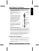
About Siemens’ Transducers The Echomax XPS F series of transducers operates in association with Siemens ultrasonic level monitoring products. hazardous seal (XPS 10 F series only) transducer The transducer operates by converting electrical pulses that are provided by the transceiver into ultrasonic pulses. When transmitted, these ultrasonic pulses reflect from the material surface and echo back to the transducer.
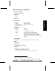
Specifications XPS 10 F Series Transducers Measurement Range: 0.
XPS 15 F Series Transducers Measurement Range: 0.45 – 15m (1.
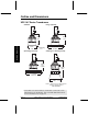
Outline and Dimensions XPS 10 F Series Transducers Standard Flange (optional) 122mm (4.8”) Outline & Dimensions 122mm (4.8”) 86mm (3.4”) radiating face Split Flange (optional) to suit ANSI standards Submergence Shield (optional) 128mm (5.0”) nominal 152mm (6.0”) to suit ANSI standards 124mm (4.9”) Refer to submergence shield instructions (Siemens’ manual number 7ML19981EG01) Note: For the XPS 10 F series transducer, a hazardous seal must be used to suit hazardous area classification.
XPS 15 F Series Transducers Standard Flange (optional) 1” NPT 304 stainless steel 185mm (7.3”) 120mm (4.7”) Split Flange (optional) 185mm (7.3”) radiating face to suit ANSI standards Submergence Shield (optional) 253mm (10.0”) to suit ANSI standards 158mm (6.2”) Refer to submergence shield instructions (Siemens’ manual number 7ML19981EG01) Note: The XPS 15 F comes equipped with a stainless steel coupling suitable for use in hazardous locations.
Mounting Recommendations Special handling precautions must be taken to protect the face of the transducer from any damage. Mount the transducer so that it is above the maximum material level by at least the blanking value (0.3m for XPS 10 F and 0.45m for XPS 15 F). Refer to the associated transceiver manual for instructions on setting the blanking value. On liquid applications, the transducer must be mounted so that the axis of transmission is perpendicular to the liquid surface.
Liquid Applications Notes: In, the examples that follow, an XPS 10 F Series transducer is shown using a hazardous seal. This seal is not supplied by Siemens. An XPS 15 F transducer can also be used in these applications, but, because it comes equipped with a stainless steel coupling, no hazardous seal is required.
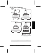
Blind Flange (XPS 10 F shown) nipple welded to bind flange hazardous seal (XPS 10 F only) Flange, gasket, hazardous seal and hardware supplied by customer. Refer to page 13 Flanged (XPS 10 F shown) hazardous seal (XPS 10 F only) Mounting factory flanged transducer bolt gasket customer flanged, flat face only nut Flange, gasket, and hardware supplied by customer. Refer to page 13 Note: Tighten the flange bolts evenly in order to ensure a good seal between the mating flanges.
Interconnection Note: Installation should only be performed by qualified personnel and in accordance with local governing regulations. Recommendations When using an XPS 15 F transducer, configure the electronic transceiver for an XCT-12. These two transducers use the same settings. Do not route cable openly. For optimum isolation against electrical noise, run cable separately in a grounded metal conduit. Seal all thread connections to prevent ingress of moisture.
2-Wire Extension (XPS 10 F shown) Hazardous Location (Class I, Div. 1, Group A,B,C,D or Class II, Div. 1, Group E,F,G) Non-Hazardous Location (Safe) junction box drain / shield metal conduit blk wht extend cable using 18 AWG shielded / twisted pair Note: When connecting to SITRANS LUT400, SITRANS LUC500, MultiRanger 100/200, or HydroRanger 200, the white, black, and shield wires are all connected separately. DO NOT tie the white and shield wires together.
Applications Liquid Applications Stilling Well / OCM blind flange air vent TS-3 * transducer standpipe bracing standpipe inlet stilling well primary element stilling well inlet Refer to page 13. A5E32725813 XPS 10/15 F Series Transducer Page 11 Applications Notes: The transducer is to be used only in the manner outlined in this instruction manual. Normally, the transducer requires no cleaning or maintenance.
Applications * the use of a TS-3 temperature sensor provides better temperature tracking in applications where the temperature can change quickly. Submergence In applications where flooding is possible, the transducer can be fitted with a submergence shield*. The shield acts as a bell to create an air pocket in front of the transducer face. The associated transceiver* interprets this as a flooding condition, and reacts accordingly. Note: Refer to transceiver manual for programming requirements.
Standpipes The standpipe length should be as short and the diameter as large as possible. As a rule of thumb, the -3 dB cone of the sound beam should not intersect the standpipe wall in applications opening into a vessel or larger area. Otherwise, additional blanking will be required to compensate for the interference zone created by the opening. Note: When using a stilling well, make sure there is no build-up, welds, couplings, or other debris on the inside of the well wall.
Volume Applications ‘Alternate’ ‘Preferred’ ‘Bad’ Maintain full level for full calibration. Above this level erroneous readings will result as level has entered blanking zone. (shaded area) tank manufacturer’s full level beam angle span: corresponds to tank manufacturer’s empty level. rise Empty level for ‘alternate locations. Below this level, echo would reflect away from the transducer. tank manufacturer’s empty level may require target to obtain empty reading discharge 1.
Water / Wastewater Applications Differential Level Pump Control Sewage Lift A5E32725813 XPS 10/15 F Series Transducer Page 15
Applications Solids Applications Typical 1. Transducer angled to avoid seams in bin wall and aimed at discharge in order to read bin when empty. 2. Avoid intersecting bin wall seams, structural members and wall irregularities. 1 bin wall seams 2 filling profile emptying profile 3. Transducer too close to material inlet. Falling material will intersect sound beam and cause erroneous readings or loss of echo.
4. On fluid like solids, aim transducer perpendicular to material surface. Applications minimal angle of repose 4 discharge 5. On dual discharge bins, aim each transducer at the discharge point.
Applications Special Storage Bin with Agitator 1. Transducer should be kept away from infeed. 2. Where agitators are in use, use the Agitator Discrimination parameter on transceivers where available. 3. Transducer should be aimed away from wall projections. 4. When used in hazardous areas, the XPS 10 F series transducer (shown) must use a hazardous seal. This seal is not supplied by Siemens.
Dryer - Wood Chips Transducer should be mounted perpendicular to slope of wood chips. 2. When used in hazardous areas, the XPS 10 F series transducer (shown) must use a hazardous seal. This seal is not supplied by Siemens. The XPS 15 F Series transducer comes equipped with a stainless steel coupling suitable for use in hazardous locations. infeed drag conveyor typical low level A5E32725813 XPS 10/15 F Series Transducer typical high level Page 19 Applications 1.
Installation Diagram Installation Diagram for the XPS 10 F Page 20 XPS 10/15 F Series Transducer A5E32725813
Notes.
Notes.
www.siemens.com/processautomation For more information www.siemens.com/level www.siemens.com/continuous-weighing Siemens AG Industry Sector 1954 Technology Drive P.O. Box 4225 Peterborough, ON Canada K9J 7B1 Subject to change without prior notice A5E32725813 Rev. AA © Siemens AG 2013 email: techpubs.smpi@siemens.com www.siemens.