Published Manual Number: MTCEXB01 • • • • • • Specified Date: 20040120 As-of Date: 20040120 Access Date: 20040120 Depth: detail Applicability: CEX Language Code: ENG01, Purpose: publication, Format: 1colA General— Electronic Coin Washerextractor Control with Seven Formulas PELLERIN MILNOR CORPORATION POST OFFICE BOX 400, KENNER, LOUISIANA 70063 - 0400, U.S.A.
Applicable Milnor® products by model number: 30010CGE 30015C4E 30015CGE 30022C4E 36021C4E
Preface Preface BICEUK01 (Published) Book specs- Dates: 20040120 / 20040120 / 20040120 Lang: ENG01 Applic: CEX i. About This Manual i. 1. i. 2. Scope This manual provides commissioning, operating, and troubleshooting instructions for Milnor® washer-extractors in the C_E model line, which are equipped with the Milnor® electronic seven formula coin washer-extractor control. See the installation manual for information on machine installation procedures and mechanical requirements.
Preface Table 1: Trademarks Ampsaver® Autolint® Autovac CBW® E-P Express® E-P OneTouch® E-P Plus® Gear Guardian® Hydro-Cushion® Mentor® Mildata® Milnet® Milnor® Miltrac Staph-Guard® System 7® Totaltrol® — End of BICEUK01 — BICEXS04 (Published) Book specs- Dates: 20040120 / 20040120 / 20040120 Lang: ENG01 Applic: CEX ii.
Preface ii. 1. Laundry Facility Provide a supporting floor that is strong and rigid enough to support—with a reasonable safety factor and without undue or objectionable deflection—the weight of the fully loaded machine and the forces transmitted by it during operation. Provide sufficient clearance for machine movement. The laundry facility must provide protection from the elements. Do not install the machine where it will be exposed to the weather.
Preface • Do not service machine unless qualified and authorized. • Lock out and tag out power at the main machine disconnect before servicing, or in accordance with factory service procedures. • Replace guards and covers before returning the machine to service and do not permit the machine to be operated with guards or covers removed. WARNING 5 : Entangle and Crush Hazards—Contact with moving components normally isolated by guards, covers, and panels, can entangle and crush your limbs.
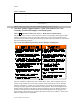
Preface 3. what to do in the event of an emergency. — End of BICEXS04 — BICEXS05 (Published) Book specs- Dates: 20040120 / 20040120 / 20040120 Lang: ENG01 Applic: CEX iii. The Customer Safety Placard—Vital Information for Coin Laundry Customers, Owners/Managers and Employees Notice 8 : Important Safety Instructions—Read and save all instructions. The customer safety placard shown in Figure 2 was affixed to your Milnor® machine in a location that is easily visible to customers.
Preface iii. 1. The Danger of Child Entrapment and Scalding There have been child entrapment incidents with machines from various manufacturers. In each instance, a small child was placed, climbed, or was helped to climb into a front loaded coin machine and the door was closed behind him. The door locked, the machine started running, and in one instance, the child was scalded to death. WARNING 9 : Entrapment/Scald Hazards— • Never let a child climb into, operate, or play around this machine.
Preface iii. 3. The Danger from Flammable Materials WARNING 11 : Fire Hazard—Never place items containing gasoline or other flammable fluids in machine. Washer-extractors are not designed to handle flammable materials. This includes goods containing flammable substances as well as flammable cleaning materials such as solvents. In either case, highly flammable vapors can be given off, especially when the material is heated.
Preface BIUUUK06 (Published) Book specs- Dates: 20040120 / 20040120 / 20040120 Lang: ENG01 Applic: CEX v. Contacting Milnor® Your first contact with any question should be your authorized Milnor dealer, but problems or special situations encountered in the field may require consultation with the Milnor factory. Written correspondence can be mailed to this address: Pellerin Milnor Corporation Post Office Box 400 Kenner, Louisiana 70063-0400 Telephone: 504-467-9591 www.milnor.com v. 1.
Preface E-mail: techpub@milnor.
Table of Contents Table of Contents Sections Figures, Tables, and Supplements Preface i. About This Manual (Document BICEUK01) i.1. Scope i.2. How to Identify this Manual and its Included Documents (Document BIUUUD13) i.3. Trademarks of Pellerin Milnor Corporation (Document BIUUUD14) ii. General Safety Requirements—Vital Information for Coin Laundry Owners/Managers and Employees (Document BICEXS04) ii.1. ii.2. ii.2.1. ii.2.2. ii.3. ii.4.
Table of Contents Sections 1.2. 1.2.1. 1.2.2. 1.3. About the Forces Transmitted by Milnor® Washerextractors (Document BIWUUI02) Foundation Considerations How Strong and Rigid? Figures, Tables, and Supplements Figure 4: How Rotating Forces Act on the Foundation Important Instructions for Pumped Chemical Inlets (Document BIWUUI01) 1.3.1. 1.3.2. 1.3.3. 1.4.
Table of Contents Sections 3.3.4. 3.4. Figures, Tables, and Supplements Error Recovery Standard Wash Cycles Supplement 3: Recycle Sequence to Reduce Vibration During Extract (Document BICEXP01) Table 4: Wash Cycles for Software Version WUC4E1A/20001-20006 Table 5: Standard Coast and Delay Times (in seconds) Chapter 4. Testing and Troubleshooting 4.1. 4.1.1. Error Codes (Document BICEXT01) How to Clear Error Conditions 4.1.2. Explanations of Error Codes 4.2. 4.2.1. 4.2.2. 4.2.3. 4.2.4. 4.2.4.1.
Chapter 1. Commissioning Chapter 1 Commissioning BICEUK02 (Published) Book specs- Dates: 20040120 / 20040120 / 20040120 Lang: ENG01 Applic: CEX 1.1. Important Owner/User Information The following two procedures must be completed before this machine is placed in service: 1. Ensure the safety of all customers and laundry personnel. 2. Customize the machine controller for the desired number of coins per wash cycle. 1.1.1.
Chapter 1. Commissioning Estimates of the maximum force normally encountered are available for each Milnor® model and size upon request. Floor or foundation sizes shown on any Milnor® document are only for ongrade situations based only on previous experience without implying any warranty, obligation, or responsibility on our part. 1.2.1.
Chapter 1. Commissioning Figure 4: How Rotating Forces Act on the Foundation Typical Rigid Machine Legend A. B. C. Direction of force Load Rotation (Frequency = RPM / 60) . Figure 4 above is intended to depict both on-grade and above-grade installations as well as models installed directly on a floor slab or on a foundation poured integrally with the slab. Current machine data is available from Milnor® upon request. All data is subject to change without notice and may have changed since last printed.
Chapter 1. Commissioning protection against harmful dribble which occurs later—when the machine is no longer in use. One foolproof solution for “dribbling” is to completely purge the appropriate chemical injection tube with fresh water after every injection, so that only fresh water (which cannot cause a problem) can dribble out. Obviously, it is the sole responsibility of the pump and/or chemical supplier (not the machine manufacturer) to furnish such a flushing device.
Chapter 1. Commissioning When calibrating injections, it is permissible to remove tubes from barbed fittings to take samples. However, always check for leaks after installing tubes and clamps. A preferable method for sampling is to install a three-way valve, or two two-way valves and a tee fitting, onto each injection tube.
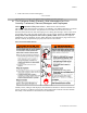
Chapter 1. Commissioning Figure 6: Rear-mounted Water and Liquid Supply Injector Figure Legend 1. 2. 3. 4. 5. 6. 7. 8. 9. .
Chapter 1. Commissioning Figure 7: Rear-mounted Water Inlet Assembly (C_E Models) Figure Legend 1. 2. 3. 4. Cold water inlet Vacuum breaker Water outlet into shell Hot water inlet . Notice 17 : Pellerin Milnor Corporation accepts absolutely no responsibility for damage to its equipment or to any textiles therein when concentrated chemicals dribble out of the injection tubes onto any part of the machine or its contents.
Chapter 1. Commissioning Pump Signal Connections 1.4.1. The microprocessor controller used on C_E models closes certain relay contacts when chemicals are desired. These signals are alternating current at the control voltage and cannot be made potential-free. Any device driven by this signal can draw up to 37 milliamperes. CAUTION 20 : Component Damage Hazard—Board components will burn out and require board replacement if devices driven by inject signals do not meet the above electrical specifications.
Chapter 1. Commissioning 1.4.2. Timer Stop Connections Timer stop is not available on machines using the C_E controller.
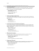
Chapter 2. Configuring Chapter 2 Configuring BICEXC01 (Published) Book specs- Dates: 20040120 / 20040120 / 20040120 Lang: ENG01 Applic: CEX 2.1. Setting the Coin Counts Milnor® coin-operated washer-extractor models in the C_E line provide seven pre-programmed wash cycles that can be selected by the user. The number of coins required for each wash cycle is controlled by DIP switches on the machine processor board (see Figure 10).
Chapter 2. Configuring 4. On the machine processor board, set the DIP switch for Formula 1 to the value established from Table 3 “DIP Switch Settings for Coin Counts”. As shown in Figure 9, to set a switch position OFF, depress the side of the switch nearer the word “OFF” until it clicks and stays depressed. To turn a switch position ON, depress the side of the switch nearer the position number. Note the DIP switch labels on the processor board and the position numbers on the DIP switches.
Chapter 2.
Chapter 3. Operating Chapter 3 Operating BICEXO01 (Published) Book specs- Dates: 20040120 / 20040120 / 20040120 Lang: ENG01 Applic: CEX 3.1. Control Panel All operator and attendant functions of the C_E electronic coin washer-extractor controller are accessible from the front control panel. The function of the various controls vary according to the position of the Attendant switch, as described in this document. Figure 11: C_E Control Panel (Typical) Controls Legend A. B. C. D. E. F. G.
Chapter 3. Operating C. Select button—scrolls through the seven available wash cycles listed on the machine control panel. The current selected wash cycle is displayed in the Select Wash Cycle window. This button is ignored if the door is open. D. Coin count window—displays the number of coins required to start the selected wash cycle if the door is closed. The coins required value counts down toward 0 as coins are accepted.
Chapter 3. Operating D. Coin count window—displays various information according to the test or operation in progress: 1. If the door is closed when the Attendant switch is turned to the horizontal position, this window displays “St” to indicate that pressing the Start button will start the wash cycle that was selected when Attendant mode was accessed. 2. When viewing the software date code, the two digits in this window show the second and third digits of the date code. 3.
Chapter 3. Operating BIWUUO01 (Published) Book specs- Dates: 20040120 / 20040120 / 20040120 Lang: ENG01 Applic: CEX 3.2. Determining Load Size Putting too much linen into a properly designed laundry washer-extractor will not overload the machine to its mechanical or electrical detriment if these guidelines are followed: 1. The goods consist of typical cotton and/or synthetic fabrics normally encountered in commercial laundering operations. 2.
Chapter 3. Operating 3.3.1. Normal Operation (Coins Required) 1. Open door and load machine. Load the machine at or near its rated capacity, as described in Section 3.2. “Determining Load Size”. Processing small loads in any washer-extractor increases the possibility of excessive vibration. 2. Close door. Securely close the loading door. Safety features on this machine are designed to notify the customer if the door is open.
Chapter 3. Operating Operation—This assembly consists primarily of a stainless steel box divided internally into three separate compartments and a supply chute which is open to the contents of the machine cylinder. When the wash cycle requires a chemical, the controller actuates an output (see Section 4.2. “Controller Inputs and Outputs”) to open one of three water valves in the injector. Water sprays into the compartment, dilutes the chemical, and overflows the compartment into the machine cylinder.
Chapter 3. Operating 3.3.2. Attendant Operation (Attendant Key Required) Two situations call for this method of operation: recurring attendant operation as when customers drop off laundry for later pickup, and restarting a terminated wash cycle without requiring additional coins. 1. Open door and load machine. Load the machine at or near its rated capacity, as described in Section 3.2. “Determining Load Size”.
Chapter 3. Operating When the wash cycle is finished, the Machine Status window displays “U” to indicate that the safety delay timer has expired and the door latch is unlocked. The decimal point on the right side of the Minutes Remaining window flashes to indicate that the door has not been opened since the wash cycle ended. Open the door and remove the goods. When the attendant opens the machine door after a wash cycle ends, the display immediately goes dark except for the Machine Status window.
Chapter 3. Operating 1. If possible, resolve the cause of the error. 2. Turn the Attendant switch to the horizontal position. 3. Return the Attendant switch to the vertical position and remove the key. Tip: To restart the selected wash cycle at the beginning, press the Start button while the switch is in the horizontal position, then turn the switch to the vertical position and remove the key.
Chapter 3. Operating Note 5: The display shows 01 Minutes Remaining until the safety delay period expires and the controller unlocks the door latch.
Chapter 4. Testing and Troubleshooting Chapter 4 Testing and Troubleshooting BICEXT01 (Published) Book specs- Dates: 20040120 / 20040120 / 20040120 Lang: ENG01 Applic: CEX 4.1. Error Codes If the machine control detects an error, the Minutes Remaining window flashes an error code corresponding to the condition, and the Machine Status window flashes E (to notify the customer that an error occurred) or U to signal the customer to unload the machine.
Chapter 4. Testing and Troubleshooting Figure 14: Normal Position of Attendant Switch Figure 15: Attendant Position of Attendant Switch Table 6: Quick Reference for Error Codes Error Code E1 E2 E3 E4 E5 E6 E7 4.1.2.
Chapter 4. Testing and Troubleshooting Display or Action Explanation If the pulse duration differs from the duration specified in the controller software or if the pulses are separated by less than one half second, the attendant must clear the error (see Section 4.1.1). E3 The level switch input is made when the controller expects it to be absent before the wash cycle begins. The attendant must clear this error (see Section 4.1.1), which is usually caused by a malfunctioning level switch.
Chapter 4. Testing and Troubleshooting BICEXT02 (Published) Book specs- Dates: 20040120 / 20040120 / 20040120 Lang: ENG01 Applic: CEX 4.2. Controller Inputs and Outputs Micro-controller inputs are received at the processor board from other machine components. Inputs that are present at the processor board usually indicate that a device is actuated. For example, Level made input originates from the water level switch and tells the processor board the machine has filled with water to the desired level.
Chapter 4. Testing and Troubleshooting Figure 16: Viewing Inputs in Attendant Mode Left Digit of Minutes Remaining Display Right Digit of Minutes Remaining Display Legend Clutch (MTA3-9) Door not locked (MTA32) Coin count (MTA3-3) 2. Inverter OK (MTA3-4) 3. Door closed (MTA3-5) 4. not used (MTA3-6) 5. Level made (MTA3-7) 6. Vibration switch tripped 7. (MTA3-8) Select button 8. Start button 9. 10. Attendant switch 11.–15. not used 0. 1. .
Chapter 4. Testing and Troubleshooting Display or Action Explanation displays the date code of the software in the machine. This keystroke also advances the controller beyond the point at which a formula can be started without inserting coins. If the intent was to start a formula without requiring coins, turn the Attendant switch to the vertical position and return it to the horizontal position, then immediately press the Start button. The software date code for this example machine is 20001.
Chapter 4. Testing and Troubleshooting Display or Action Explanation from the input status display begins the output test. Tip: In the output test, the coin count window flashes 00 unless the controller is counting down a safety delay. During the delay period of up to 100 seconds, the coin count window is dark and the decimal point in the Machine Status window flashes to indicate that the controller is working. When the safety delay time expires, the Coin Count window again flashes 00.
Chapter 4. Testing and Troubleshooting 4.2.4.1. Functional Test 12—This test is useful for checking the water valves, drain valves, door lock, and wash speeds. The test executes as described below: Display or Action Explanation from output test 11 (chemical 3), turns off output 11 and advances to functional test 12 initiates the test. 1. Door locks, drain closes, inverter enabled, hot and cold water valves open. 2. After four seconds of dwell time, the basket turns clockwise for 15 seconds. 3.
Chapter 4. Testing and Troubleshooting 4.2.4.2. Functional Test 13—This test checks the door lock, inverter speeds, and vibration switch. The test executes as described below: Display or Action Explanation from functional test 12, turns off test 12 and advances to functional test 13. initiates the test. 1. The door locks, the inverter is enabled, and the basket turns clockwise at wash speed for 25 seconds. 2. The basket accelerates to drain speed for 25 seconds. 3.