
Installation manual

Chapter 4. Troubleshooting
PELLERIN MILNOR CORPORATION
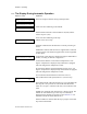
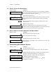
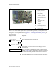
Figure 7: Processor Board
Photograph of Typical Processor Board Legend
.
A. Display connectors
B. Switch panel connector
C. DIP switches
D. Temperature probe
connector (E-P Plus
models only)
E. Pressure transducer for
level (E-P Plus models
only)
F. Capacitor to retain
memory
G. Outputs to chemical
pumps
H. Standard outputs
I. Operator signal buzzer
J. CPU chip
K. Input connector
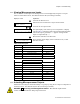
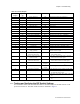
There is one unique number which identifies each possible combination of on/off settings at the
DIP switch. While the industry configuration (switch 1 through switch 4) is readily available from
the Software version mode (described in Section 4.1.2 “Determining the Software Version”), the
settings of other switch positions are only apparent from this display or by visually inspecting the
processor board.
Display or Action Explanation
`
Enters the Manual menu from the Run mode.
MANUAL MENU
1 SOFTWARE DATE CODE
This is the first item of the Manual menu.
w
,
w
Scrolls down to the Test DIP Switch item.
MANUAL MENU
4 TEST DIP SWITCH
This is the Test DIP Switch item of the Manual menu.
`
+
\
Accesses the Test DIP Switch function and displays the DIP
switch setting.
052
This is an example of the DIP switch display. Referencing this
number in Table 15 shows that the sample machine is configured
for Restaurants Laundry, and that switch positions 5 and 6 are
enabled.
z
Terminates the Manual menu and returns controller to Run mode.