
Installation manual


Chapter 4. Troubleshooting
PELLERIN MILNOR CORPORATION
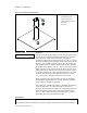
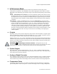
Figure 8: Level Sensor Testing Fixture
Fixture Legend
.
A. graduated tube from
pressure transducer
B. cylinder filled to near top
with water
C. base plate
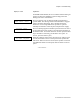
Display or Action Explanation
R00088 A:01.7 C:01.0
R00099 A:082F [TEMP]
The top line of the display applies to the level sensing circuit. The
“R” and the five characters immediately following it on the top
line indicate the voltage being delivered by the pressure
transducer on the processor board (see Figure 7). The “A” value is
the actual instantaneous level read by the transducer. Because this
display is only available when the drain is open, the actual level
will normally reflect no water in the machine cylinder, although
the number will be above 0. The “C” value is a calculated average
of the transducer levels, used to negate the effects of rising and
falling water levels caused by the reversing wash motion. Again,
in normal conditions, this value will reflect that there is no water
in the machine, although it may fluctuate between two values
(e.g., 1.0 and 2.0) as it adjusts to the nearest whole inch.
When using the level sensor test fixture (Figure 8), the display
should indicate approximately the level to which the graduated
plastic tubing is inserted into the water.
The bottom line of the display applies to the temperature sensing
circuit. Similar to the “R” value of the top line, the first six
characters of the bottom line indicate the voltage being delivered
by the temperature probe to the processor board (see Figure 7).
The “A” value on the bottom line is the temperature in degrees
Fahrenheit detected by the temperature probe.
Supplement 5
Testing the Pressure Transducer Circuit
The pressure transducer (illustrated in Figure 9) outputs a microvolt-level signal that increases