
Installation manual


Chapter 4. Troubleshooting
PELLERIN MILNOR CORPORATION
proportionally according to the pressure in the plastic tube. The instrumentation amplifier
magnifies this signal by a factor of 1000 for the microprocessor. Because only very sensitive
voltmeters are capable of reading a signal of less than one millivolt, better results are available by
measuring the output voltage from the instrumentation amplifier. This procedure is described
below:
CAUTION 32 : Electrocution and Electrical Burn Hazards—Electric box
doors—Operating the machine with any electric box door unlocked can expose high voltage
conductors inside the box.
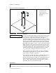
1. Locate the instrumentation amplifier on the processor board. This is a small integrated circuit
chip with eight leads in socket IC20, near the pressure transducer.
2. Set your digital voltmeter to read a maximum of 5 volts DC. The output of this component,
even when failed, will not exceed 5 VDC.
3. Locate pin 6 on the instrumentation amplifier. Note the notch in one end of the amplifier
chip. If the board is oriented so the notch on the chip is at the left side of the chip, then pin 1
is the leftmost pin on the bottom row. Count pins counterclockwise to pin 6. If the orientation
of the board is maintained (pin 1 at the lower left), then pin 6 will be the second chip from the
right on the top row. This is the amplifier output pin.
4. Put the positive lead from your voltmeter on pin 6 of the amplifier chip, and the negative lead
to a reliable electronic ground. Pin 5 (rightmost pin on top row) of the amplifier chip provides
a suitable ground.
The output voltage read on the meter should be approximately 0.1 volts per inch of water in the
machine cylinder. That is, if the machine is filled to a level of 4 inches (10 cm), the voltage
measured between pins 5 and 6 of a functioning amplifier will be about 0.4 volts.
Note 13: If your voltmeter is capable of reading microvolts, the transducer can be tested without the effect
of the instrumentation amplifier. The notched pin on the transducer is pin 1 (ground). The reference
voltage of slightly less than 1.5 VDC is applied to pin 3. Pins 2, 3, and 4 will all read the reference voltage
relative to pin 1. The output voltage between pins 2 and 4 should equal approximately 0.1 millivolt per
inch of water.
If the voltage is lower than expected, first check for leaks in the plastic tube connected to the
pressure transducer. If no leaks are found, or if the voltage is significantly higher than expected,
replace the processor board.