Speed HPTx Wireless Data Link for Meter Reading FCC ID: MLLSPEEDHPTX15-17 User Manual
Miltel Communications Ltd. January 2001 Table of Contents Chapter 1 .................................................................................................Introduction 4 1.1 Purpose and Use........................................................................................ 4 1.2 System General Description........................................................................ 4 Chapter 2 Theory of Operation..................................................................................
-
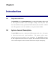
Chapter 1 Introduction 1.1 Purpose and Use The Speed HPTx (FCC ID: MLLSPEEDHPTX15-17) is a data link transmitter that is used for data acquisition in Miltel’s water consumption readings collection system. This device is installed on-site by a professional field technician, thus it includes technical terms. The equipment is not to be installed by a non-professional individual. 1.2 System General Description The Speed HPTx system is a computerized fully automatic radio device.
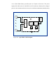
Chapter 2 Theory of Operation 2.1 General Description The Speed HPTx is the first link in the water readings collection system. It is an independent unit that does not require an external power source, wiring, or the preparation of an infrastructure. The unit is installed in proximity to the water meter/s and is connected to several adjacent meters. Figure 2-1 (see next page) shows a typical installation of a Speed HPTx unit, connected to several meters (of various types) at a single location.
Transmitter (Speed Clamp Figure 2-1: Speed HPTx Typical Installation 2.2 Block Diagram Description 2.2.1 General Figure 2-2 describes the block diagram of the Speed HPTx unit.
A 3.6 volts Lithium battery provides power to all parts of the device. The power supply for the RF section is controlled via the Tx switch (not shown), thus cutting of power to the transmitter unless necessary for actual data transmission (standby mode).
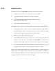
2.2.2 Digital Section The digital section of the Speed HPTx performs the following functions: ! Samples reed switches to detect short/open from each meter. ! Accumulates number of pulses for each meter separately ! Stores data (including battery and tamper alarms) and stores information internal memory ! Interfaces the data to the RF section The digital section is based on a central controller which accepts the following inputs: a.
The controller gathers the data for several hours before initiating a transmission. If any of the counters has advanced by more than a preset value, or any alarm (tamper or low voltage) has been received, the controller generates a single message immediately. Any further message will include alarm information along with counter data, if alarm condition still exists. Note: The duration interval between two transmissions is always greater than 1 Hr. a.
Chapter 3 Technical Characteristics 3.1 Technical Specification 3.1.1 Electrical Max Effective Radiated Power (ERP) 3.1.2 50 mW FCC 90.205(d) ) (Complies with Output frequency 150-170 MHz Carrier wave modulation 2 Level FSK Power supply Lithium battery, 3.6 Volt Input Channels 1-10 Water Meters Compatibility Any type of meter which has a reed relay switch (pulsed output) Transmission Duration 0.8 Sec. Max. Duration between Transmissions 30 Min.
3.2 Width 8 cm. Depth 3 cm. Weight (excluding clamp) 100 gr. Weight (including clamp) 500 gr. Clamp material Stainless steel Clamp screws Protected from dismantling Label Contents (see file: Speed HPTx ID Label) FCC ID: MLLSPEEDHPTX15-17 Mode: Speed HPTx S/N: YY-nnnnnn Miltel Communications Ltd.
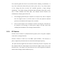
Chapter 4 Installation Instructions 4.1 General The Speed HPTx is installed by a professional technician. Several possibilities for installation have been programmed into the system in order to provide solutions for installation of various types of water meters. The Speed HPTx installation is performed using a stainless steel clamp that enables connection to pipelines of different diameters (0.75", 1.00", 1.50" or 2.00").
Note Connect each pair of wires to the respective terminals; note the connections for future reference. 4) Close the unit's box cover. 5) Perform functional radio test by touching box corner with strong magnet (trigger transmission). Verify correct reception of data at base station (concentrator). Update water actual readings for the respective meter. 6) Close the four screws fastening the cover. 7) Insert plastic protection plugs.