Figure 2-1: Speed HPTx Typical Installation
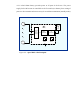
2.2 Block Diagram Description
2.2.1 General
Figure 2-2 describes the block diagram of the
Speed HPTx
unit. This device consists
of two major sections, all using a common power source:
! Digital section (Micro Controller)
! RF section
Transmitter
(
Speed
Clamp