
User Manual


The controller gathers the data for several hours before initiating a transmission. If
any of the counters has advanced by more than a preset value, or any alarm (tamper
or low voltage) has been received, the controller generates a single message
immediately. Any further message will include alarm information along with counter
data, if alarm condition still exists. Note: The duration interval between two
transmissions is always greater than 1 Hr.
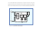
a. The messages generated by the controller are 16 bytes each, and are outputed
from the digital section to the RF section as serial data (RS-232 standard
protocol) via the DATA OUT output of the controller.
b. The Tx control output of the controller is used for activating the TX switch for
the duration of the message, to enable power supply to the RF section thus
enabling the transmission of the message (transmit mode).
2.2.3 RF Section
The RF section consists of a phased-locked loop (PLL) and a low-power amplifier
connected to an integral antenna.
The PLL reference is driven by a 20.0 MHz. crystal oscillator. This reference is
phase-compared by the Phase Detector with the divided output frequency.
The phase detection signal from the detector is filtered by the PLL Loop Filter and
then summed with the shaped signal received from the digital section by the Sum
Network block. The output of the Sum Network is the control signal that modulates
and locks the Voltage Control Oscillator (VCO).