
User's Manual


Speed TxRx User Manual
Miltel Communications Ltd. 6
2.2 Block Diagram Description
2.2.1 General
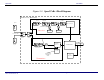
Figure 2-1 describes the block diagram of the Speed Tx Rx unit. RF is received or transmitted
from either antennas upon the controller selection. Two antennas are used to improve
performance in urban environment where shadowing, due to tall buildings, generates sever
multipath effect. This effect can reduce the received signal by more than 30dB, thus by switching
antennas periodically the transceiver improves reception.
2.2.2 Transmitter
A PLL IC ( MC13176 from Motorola Semiconductors) gets the reference, 13.56MHz, from a
crystal oscillator and locks the VCO output, divided by 32, to the crystal frequency. Therefore,
the output frequency equals Crystal_frequency x 32 = 433.92 MHz.
The message digital data from the Controller is shaped and modulates the VCO frequency. The
VCO output is attenuated by a resistive Π Attenuator. A 6 pole low pass filter that rejects the
harmonics, further filters the output. The output is routed through a T/R switch and a diversity
switch to the output/input UHF connectors.
Coaxial cables connect the half-wavelength dipole antennas with the Transceiver. All the
emissions parameters are in compliance with FCC part15C specifically the limitations set by
15.231(e). When the Transceiver is in the receive mode the voltages to the Transmitter are off.