Speed Tx User Manual Speed Tx Low Power Wireless Data Link FCC ID: SPEEDTx433L1 User Manual Miltel Communications Ltd. Miltel Communications Ltd.
Speed Tx User Manual Table of Contents Chapter 1 Introduction...................................................................................................3 1.1 Purpose and Use ............................................................................................3 1.2 System General Description ...........................................................................3 Chapter 2 Theory of Operation .....................................................................................4 2.
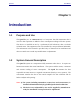
Speed Tx User Manual Chapter 1 Introduction 1.1 Purpose and Use The Speed Tx (FCC ID: SPEEDTx433L1) is a low-power data link transmitter that is used for data acquisition in Miltel’s water consumption readings collection system. This device is installed on-site by a professional field technician, thus it includes technical terms. The equipment is not to be installed by a non-professional individual.
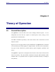
Speed Tx User Manual Chapter 2 Theory of Operation 2.1 General Description The Speed Tx is the first link in the water readings collection system. It is an independent unit that does not require an external power source, wiring, or the preparation of an infrastructure. The unit is installed in proximity to the water meter/s and is connected to several adjacent meters.
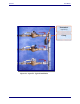
Speed Tx User Manual Transmitter (Speed Tx) Clamp Figure 2-1: Speed Tx Typical Installation Miltel Communications Ltd.
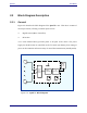
Speed Tx User Manual 2.2 Block Diagram Description 2.2.1 General Figure 2-2 describes the block diagram of the Speed Tx unit. This device consists of two major sections, all using a common power source: Digital section (Micro Controller) RF section A 3.6 volts Lithium battery provides power to all parts of the device.
Speed Tx 2.2.2 User Manual Digital Section The digital section of the Speed Tx performs the following functions: Samples reed switches to detect short/open from each meter. Accumulates number of pulses for each meter separately Stores data (including battery and tamper alarms) and stores information internal memory Interfaces the data to the RF section The digital section is based on a central controller which accepts the following inputs: a.
Speed Tx User Manual The controller gathers the data for several hours before initiating a transmission. If any of the counters has advanced by more than a preset value, or any alarm (tamper or low voltage) has been received, the controller generates a single message immediately. Any further message will include alarm information along with counter data, if alarm condition still exists. Note: The duration interval between two transmissions is always greater than 1 Hr. a.
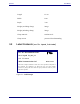
Speed Tx User Manual Chapter 3 Technical Characteristics 3.1 Technical Specification 3.1.1 Electrical Max Effective Radiated Power (ERP) 1.4 µW Peak (Complies with FCC 15.231(e) ) Output frequency 433.92 MHz Carrier wave modulation 2 Level FSK Power supply Lithium battery, 3.6 Volt Input Channels 1-8 Water Meters Compatibility Any type of meter which has a reed relay switch (pulsed output) Transmission Duration 0.8 Sec. Max. Duration between 1 Hr. Min. Transmissions 3.1.
Speed Tx 3.2 User Manual Length 11 cm. Width 8 cm. Depth 3 cm. Weight (excluding clamp) 200 gr. Weight (including clamp) 500 gr. Clamp material stainless steel Clamp screws protected from dismantling Label Contents (see file: Speed_Tx ID Label) FCC ID: MLLSPEEDTx433L1 Model: Speed Tx_433_L1 S/N: YY-nnnnnn Miltel Communications Ltd. Made in Israel This device complies with Part 15 of the FCC rules.
Chapter 4 Installation Instructions 4.1 General The Speed Tx is installed by a professional technician. Several possibilities for installation have been programmed into the system in order to provide solutions for installation of various types of water meters. The Speed Tx installation is performed using a stainless steel clamp that enables connection to pipelines of different diameters (0.75", 1.00", 1.50" or 2.00").
Speed Tx User Manual b. For wall mounting of the unit, install the base directly onto the wall or surface using the two steel screws. 3) Connect the wire pairs from the water meters to the terminal blocks on the PCB. Up to four such pairs can be connected, with unused connections left open (i.e., no termination is required). Note Connect each pair of wires to the respective terminals; note the connections for future reference. 4) Close the unit's box cover.