
User's Manual

Speed Tx User Manual
Miltel Communications Ltd. 6
2.2 Block Diagram Description
2.2.1 General
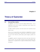
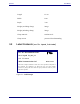
Figure 2-2 describes the block diagram of the Speed Tx unit. This device consists of
two major sections, all using a common power source:
Digital section (Micro Controller)
RF section
A 3.6 volts Lithium battery provides power to all parts of the device. The power
supply for the RF section is controlled via the Tx switch (not shown), thus cutting of
power to the transmitter unless necessary for actual data transmission (standby mode).
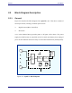
Figure 2-2: Speed Tx Block Diagram
Meter
1
Meter
n
Sensing
and
Support
Circuitry
Micro-
Controller
RF
Transmitter
Antenna
Battery
Device Enclosure
Magnetic
Switch
Tamper
Switch