
User Manual


8 9
WARNING!
TOOL ASSEMBLY
To reduce the risk of injury,
always unplug tool before attach-
ing or removing accessories
or making adjustments. Use only
specifically recommended acces-
sories. Others may be hazardous.
Removing and Replacing Quik-Lok
®
Cords (Fig. 1) (Cat. No. 0100-20,
0101-20, 0202-20, 0301-20, 0302-20
MILWAUKEE
's exclusive Quik-Lok
®
Cords
provide instant field replacement or
substitution.
Fig. 1
1. To remove the Quik-Lok
®
Cord, turn the
cord nut 1/4 turn to the left and pull it
out.
2. To replace the Quik-Lok
®
Cord, align the
connector keyways and push the con-
nector in as far as it will go. Turn the
cord nut 1/4 turn to the right to lock.
Adjusting the Side Handle (Fig. 2)
(Cat. No. 0200-20, 0202-20, 0299-20,
0300-20, 0301-20, 0302-20)
1. Turn the side handle counterclockwise
to loosen.
2. Slide the side handle assembly forward
over the chuck and rotate to the de-
sired angle.
3. Slide the side handle back to the
gearcase and position the locking keys
into the detents. The locking keys help
prevent the handle from slipping.
NOTE: The side handle ring must clear
the chuck.
4. Turn the side handle clockwise to
tighten.
NOTE: Always use the side handle for
best control.
WARNING!
To reduce the risk of injury, al-
ways use a side handle when us-
ing this tool. Always brace and
hold securely.
Gearcase
Side handle ring
Side handle
Locking keys
Detents
Fig. 2
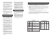
FUNCTIONAL DESCRIPTION
1. Chuck
2. Side handle*
3. Nameplate
4. Lock button
5. Trigger
6. Forward/Reverse switch
* Cat. Nos. 0200-20, 0202-20, 0299-20, 0300-20,
0301-20, 0302-20 only
1
2
3
4
5
6