
Manual


4
5
6
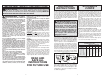
1. Handle
2. Exhaust port
3. Tank latch
4. Intake port
5. Tank
6. Utility Outlet
(Cat. No. 8936-20 only)
* For Cat. No. 8936-20 with onboard outlet: The entire unit is rated at 12 amps. The vacuum motor is rated at 9.5 amps.
The outlet on the motor head is rated at 8 amps.
Cat. No.
Volts
AC Amps For Materials
Tank Capacity
Gallons
Air Flow
Cubic Feet per Minute
Sealed Suction
in Water
8936-20
8938-20
8950
8955
120
120
120
120
12*
7.4
8
8
Wet or Dry
Wet or Dry
Wet or Dry
Wet or Dry
7.5
9
8
10
190
100
143
143
60"
80"
45"
45"
3
2
1
4
5
1
2
3
5
4
WARNING To reduce
the risk of injury, always unplug tool before
changing or removing accessories. Only use
accessories specifi cally recommended for
this tool. Others may be hazardous.
Assembling Dolly (Cat. No. 8955)
Assemble as shown in the diagram. You will need
a hammer and a phillips screwdriver.
Installing Handle (Cat. No. 8955)
You will need either a fl at blade screwdriver or a
socket driver and a wrench or a pair of pliers.
Assembling Dolly (Cat. No. 8938-20)
Assemble as shown in the diagram. You will need:
(2) 1/2 inch open end wrenches, (2) 7/16 inch open
end wrenches, or a socket set and a hammer.
1. Place wheels on rear frame (B) by tapping in the
axle (C), fi tting the wheel (D) on the axle and
tapping a cap nut (E) on with a hammer.
2. Align front frame (F) and rear frame (B) so that
they fi t together and fi t lip of tank (H) into the
grooves in front and rear frames.
3. Secure frame (B and F) to the tank by placing
the hex bolts (I) through the holes in dolly and
securing them with nut (L) and washer (K) as
shown.
4. Insert caster (G) and push down until caster
snaps into place.
Fig. 1
A
E
D
C
F
G
B
H
J
K
L
I
Fig. 2
1. Place dolly handle between tank and side handle
on either side of the tank.
2. Fasten tightly with slotted hex head screws.
Fig. 3
SPECIFICATIONS
FUNCTIONAL DESCRIPTION
ASSEMBLY
Hertz
Amps
Underwriters Laboratories, Inc.
United States and Canada
SYMBOLOGY
1. Insert 2-1/2 inch long bolt through the center hole
in rear frame, attach split lockwasher, and nuts.
Tighten securely.
2. Attach handle brace to back of rear frame with
5/8 inch long machine screws, lockwashers, and
nuts (Finger tight only).
3. Position main frame inside rear frame. Attach
with (2) 5/8 inch long machine screws, lockwash-
ers and nuts in both sides. Tighten securely.