
Operator’s Manual


5
SPECIFICATIONS
Cat. No. ..................................................... 0725-20
Volts .............................................................. 28 DC
Battery Type .....................................M28™or V28
®
Charger Type ....................................M28™or V28
®
Rated RPM ......................................................8000
Spindle Thread Size .................................... 5/8"-11
Max Capacity .........................................4-1/2"x1/4"
ASSEMBLY
WARNING
Recharge only with the charger
specied for the battery. For spe-
cic charging instructions, read the operator’s
manual supplied with your charger and battery.
Removing/Inserting the Battery
To remove the battery, push in the release buttons
and pull the battery pack away from the tool.
WARNING
Always remove battery pack before
changing or removing accessories.
To insert the battery, slide the pack into the body
of the tool. Make sure it latches securely into place.
WARNING
To reduce the risk of injury when
grinding, always use properly in-
stalled guards.
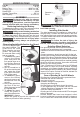
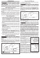
Removing/Installing/Adjusting the Guard
This tool is shipped with
Spindle plate
Retaining
tab
the guard installed. The
guard must be used
when using the tool as a
grinder. The guard may
be removed when using
tool as a sander.
1. To remove the guard,
remove the battery
pack and place the
tool upside down on a
level surface. Remove
any accessories from
spindle.
2. Use a screwdriver to
lift up the retaining tab
and rotate the guard
to the front of the tool.
Pull off the guard.
3. To install the guard,
remove the battery
pack and remove any
accessories from the
spindle.
4. Line up the guard from
the front of the tool.
Slide the guard under
the spindle plate.
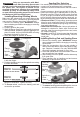
5. To adjust the guard,
rotate the guard to
one of the detent slots.
WARNING! Always
adjust the guard to provide the operator with
maximum protection while operating.
Operator's
Zones
WARNING
To reduce the risk of injury, always
use a side handle when using this
tool. Hold securely.
Installing Side Handle
The side handle may be installed on either side of
the gear case. Position the side handle in the loca-
tion which offers best control and guard protection.
To install, thread side handle into side handle socket
and tighten securely.
WARNING
To reduce the risk of injury, the
operator should be instructed in
the use, care and protection of grinding wheels.
Grinding Wheel Selection
Use grinding wheels, and accessories that are:
• correct size as written on tool’s nameplate.
• rated at or above the RPM listed on the tool’s name-
plate.
• correct accessory, wheel type and grit for the job.
Grinding is the cutting action of thousands of abrasive
grains on the face of a grinding wheel. When grinding
metals such as steel and iron, choose an aluminum
oxide grinding wheel. Select a silicon carbide grinding
wheel for stone and concrete. Use cotton reinforced
wheels for non-ferrous metals.
Type 1 Reinforced 1/8" thick or less Cut-Off Wheels
are suited for small cut-off and shallow notching
operations only. Always handle wheels carefully to
avoid damage. Before installing any wheel, always
inspect it for cracks. If wheel is cracked, discard it to
prevent others from using it.
Care of Grinding & Cut-Off Wheels
Grinding/cut-off wheels should be protected from:
• wetness and extreme humidity
• any type of solvent
• extreme changes in temperature
• dropping and bumping
Grinding and cut-off wheels should be stored:
• in an organized way so wheels can be removed
without disturbing or damaging other wheels
• with their safety information
Grinding and cut-off wheels should NOT be dropped,
rolled or bumped.
Discard wheels that have been dropped, rolled,
bumped, subjected to extreme changes in tempera-
ture, or come into contact with solvents or wetness.