
Service Parts List S/N A74A
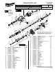


SERVICE NOTES
Disassembly:
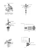
33, 71 When, removing shift lever (71) from gear case cover (33) follow
instructionslistedonservicebulletin.[seeg.1]
19,33 Releaselockingtabsongearboxcover(33)usingtwoatbladed
screwdriverswhenremovingfromgearboxassembly(19).[seeg.3]
4, 21, 37 Remove armature pinion (37) from armature (21) using Special
Service Fixtures 61-10-0035. Note: Place separator plates 61-10-0011
underballbearing(4)asillustrateding.5.
40,53,56,80 Toremoveretainingring(80)fromspindle(53)useservicexture
61-30-0290. Note: Spindle gear / clutch gear (40) must be
compressed against Belleville spring washers (56) before retaining
ringcanberemoved.(seeg.8)
21, 23, 35 Remove carbon brushes (23) from motor housing (35) prior to
removing armature assembly (21).
Reassembly:
88, 97 Small diameter end of striker (88) must face stop washer (97) in assembly.
53, 97 Chamfer side of stop washer (97) to face front of spindle (53).
31, 5 Raised bosses on mount bracket (58) must face crankcase (31) in assembly.
33, 71 When reinstalling shift lever (71) into gearcase cover (33) follow
instructionsshowning.2.
9, 10, 11, 12, 13, Apply Blue Loctite ® METCo part # 44-22-0090 to fasteners listed if
14, 15, 16, 17 removed and being reinstalled. New fasteners in service kit will not
require additional Loctite®.
81, 83 Taper of holding ring (83) to face spring ring (81) in assembly.
57, 59 Wide portion of conical spring (57) to face plate (59).
36, 51, 92 When reassembling bevel gear (36) onto reduction gear shaft (51) a
.001 - .002 clearance must be maintain between bevel gear (36) and
spacer(92).[seeg.2]
Coat
with
"P"
Coat
with
"Q"
Coat
with
"P"
Coat
with
"Q"
Coat
with
"Q"
Coat
with
"P"
Coat with "P"
Coat
with
"P"
Coat
with
"Q"
Coat
with
"P"
Place approx.
3/4 oz. type "P"
Coat
with
"P"
Coat with "P"
Place approx.
1/4 oz. type "P"
Place approx.
1/2 oz. type "P"
Service Kit 14-46-0756 Contains:
Fig. Part No. Desc. Of Part Qty.
9 05-74-0183 Screw 2
10 05-74-0215 Screw 4
11 05-74-0220 Screw 1
12 05-74-0225 Screw 2
13 05-74-0230 Screw 2
14 05-74-0460 Screw 2
15 05-74-0470 Screw 2
16 05-74-0685 Screw 4
17 05-74-0715 Screw 5
23 22-18-0690 Carbon Brush Set 1
41 34-40-0083 O-Ring 1
42 34-40-0130 O-Ring 1
43 34-40-0430 Spring Ring 1
44 34-40-0435 O-Ring 1
45 34-40-0440 O-Ring 1
46 34-40-0445 O-Ring 1
47 34-40-1025 O-Ring 1
48 34-40-1305 O-Ring 1
49 34-40-4451 O-Ring 1
50 34-40-4465 Seal Ring 1
60 42-52-0420 Dust Cap 1
62 42-76-0830 Thrust Collar 1
65 42-96-0205 Rubber Sleeve 1
66 42-96-0210 Sleeve 1
68 43-44-0875 Seal 1
70 43-84-0443 Felt 1
79 44-90-0183 Spring Ring 1
80 44-90-0350 Spring Ring 1
86 45-06-0090 Seal Ring 1
87 45-06-0095 Seal Ring 1
98 45-88-1775 Spring Ring 1
99 45-88-1780 Spring Ring 1
49-08-5350 Type "P" Grease 1
49-08-4255 Type "Q" Grease 1
PAGE 5 OF 6
BULLETIN NO. 54-24-7020 Dec. 2008
4, 87 Flared edge of seal (87) to face ball bearing (4) in assembly.
53,56 ReassembleBellevilleSpringwashers(56)ontospindle(53)asshowning.7.
21,25 Whenreplacingafan(25)onarmatureassembly(21),refertoillustrationshowning.6forpressdimensions.
43, 51 Install a new spring ring retainer (43) if removed from reduction gear shaft (51).
NOTE: CHECK THE CLUTCH TORQUE. CLUTCH MUST SLIP AT 17 TO 26 FT. LBS.
AT THE SPINDLE, CHECKED CLOCKWISE AS VIEWED FROM THE FRONT OF
THE TOOL. SELECTOR KNOB MUST BE SET TO THE HAMMER ONLY SETTING.
LUBRICATION
Type "Q" grease, No. 49-08-4255
Coat with a total of 1/4 oz.
Type "P" grease, No 49-08-5350
Cover with a total of 1-3/4 oz.
(1-1/2 oz. to ll, 1/4 oz. to coat)
TORQUE SPECIFICATIONS
Screws in plastic 15 in. lbs.
Screws in metal 22 in. lbs. Use Blue Loctite® 242
Metco Cat. No. 44-22-0090
Removing the 1 Bring the shift lever (2) into the
shift lever Drill-Only position (Illustration A).
2 Press in and hold the locking
device (3) (Illustration A) and turn
the shift lever past the drill icon
(Illustration B) until the shift lever (2)
can be pulled from the housing.
3 Remove the O-ring (1).
Installing the 1 Lightly grease the O-ring (1) and
shift lever install it into the Shift Lever (2).
2 Position the triangle located on
the shift lever to the Hammer / Drill
icon and insert it into the gearcase
(Illustration A). Press the locking
device and turn clockwise
(Illustration B) until the shift lever (2)
engages audibly. After that, turn
it back to the required position (C)
and release the locking device.