
Use and Care Manual


3
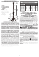
Recommended Minimum Wire Gauge
For Extension Cords*
Extension Cord Length
Nameplate
Amperes
25' 50' 75' 100' 150'
0 - 2.0
2.1 - 3.4
3.5 - 5.0
5.1 - 7.0
7.1 - 12.0
12.1 - 16.0
16.1 - 20.0
18
18
18
18
16
14
12
18
18
18
16
14
12
10
18
18
16
14
12
10
--
18
16
14
12
10
--
--
16
14
12
12
--
--
--
* Based on limiting the line voltage drop to ve volts at 150%
of the rated amperes.
READ AND SAVE ALL INSTRUCTIONS
FOR FUTURE USE.
Double Insulated Tools (Two-Prong Plugs)
Tools marked “Double Insulated” do not require
grounding. They have a special double insulation
system which satisfies OSHA requirements and
complies with the applicable standards
Fig. A
Fig. B
of Underwriters Laboratories, Inc., the
Canadian Standard Association and
the National Electrical Code. Double
Insulated tools may be used in either
of the 120 volt outlets shown in Figures
A and B.
ASSEMBLY
WARNING Recharge only with
the charger specied for the battery. For specic
charging instructions, read the operator’s manual
supplied with your charger and battery.
Inserting/Removing Battery Pack
Insert the battery pack by sliding battery pack into the
battery bay. Insert the battery pack until the battery
latches lock.
To remove the battery pack, press in both battery
latches and slide the battery pack out of the battery bay.
Inserting/Removing Extension Cord
To operate the light on AC power, extend and lock
legs. Plug a suitable extension cord into the AC
inlet . To disconnect the extension cord, press the
switch button to turn off the light, then remove the
cord from the inlet.
NOTE: When an extension cord is plugged into the light,
the light will automatically run on AC power.
WARNING
To reduce the risk of
injury, do not look directly into the light when the
light is on.
To reduce the risk of injury, always fully extend and
lock legs into position before raising the poles.
Light may tip and cause injury.
To reduce the risk of injury, keep hands clear of
the housing area when collapsing the extension
poles. Head may descend rapidly, pinching hands
and ngers.
SPECIFICATIONS
Cat. No. ......................................................2132-20
Volts ............................................................... 12 DC
Use only MILWAUKEE M12™ Li-Ion battery packs
AC Input Volts ....................................................120
DC Input Volts......................................................12
AC Input Amps....................................................0.5
Recommended Ambient
Operating Temperature ......................0°F to 125°F
FUNCTIONAL DESCRIPTION
1
2
8
1. Head
2. Extension poles
3. Battery bay
4. Legs
5. AC inlet (not shown)
6. Carrying handle
7. Leg release buttons
8. Switch
6
3
4
5
7
EXTENSION CORDS
Grounded tools require a three wire extension
cord. Double insulated tools can use either a two
or three wire extension cord. As the distance from
the supply outlet increases, you must use a heavier
gauge extension cord. Using extension cords with
inadequately sized wire causes a serious drop in
voltage, resulting in loss of power and possible tool
damage. Refer to the table shown to determine the
required minimum wire size.
The smaller the gauge number of the wire, the greater
the capacity of the cord. For example, a 14 gauge
cord can carry a higher current than a 16 gauge cord.
When using more than one extension cord to make
up the total length, be sure each cord contains at
least the minimum wire size required. If you are using
one extension cord for more than one tool, add the
nameplate amperes and use the sum to determine
the required minimum wire size.
Guidelines for Using Extension Cords
• Be sure your extension cord is properly wired and in
good electrical condition. Always replace a damaged
extension cord or have it repaired by a qualied
person before using it.
• Protect your extension cords from sharp objects,
excessive heat and damp or wet areas.