
Use and Care Manual


4
5
Operating Temperature
Battery and Charger ....................
32°F to 150°F
(0°C to 65°C)
Battery and Tool ................................0
°F to 167°F
(-18°C to 75°C)
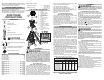
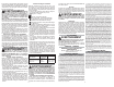
FUNCTIONAL DESCRIPTION
1
3
4
2
6
8
10
5
7
1. Heads
2. Extension poles
3. Extension latches
4. Control panel
5. Upper handle
6. Leg release button
7. Legs
8. Carrying handle
9. AC outlet door
10. Battery bay/
Charger
11. Battery power
indicator
12. Brightness indicator
13. AC power indicator
14. Decrease brightness
button
15. Power button
16. Increase brightness
button
11
13
14
15
16
9
12
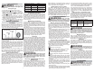
GROUNDING
WARNING
Improperly con-
necting the grounding wire can result in the
risk of electric shock. Check with a qualifi ed
electrician if you are in doubt as to whether the
outlet is properly grounded. Do not modify the
plug provided with the tool. Never remove the
grounding prong from the plug. Do not use the
tool if the cord or plug is damaged. If damaged,
have it repaired by a MILWAUKEE service facility
before use. If the plug will not fi t the outlet, have
a proper outlet installed by a qualifi ed electrician.
Grounded Tools:
Tools with Three Prong Plugs
Tools marked “Grounding Required” have a three
wire cord and three prong grounding plug. The plug
must be connected to a properly grounded outlet
(See Figure A). If the tool should electrically mal-
function or break down, grounding provides a low
resistance path to carry electricity away from the
user, reducing the risk of electric shock.
The grounding prong in the plug is connected through
the green wire inside the cord to the grounding sys-
tem in the tool. The green wire in the cord must be
• Never service damaged battery packs. Service of
battery packs should only be performed by the manu-
facturer or authorized service providers.
SPECIFIC SAFETY RULES
• Warning - The lens may get hot during use. To reduce
the risk of burns, do not touch hot lens.
• Maintain labels and nameplates. These carry impor-
tant information. If unreadable or missing, contact a
MILWAUKEE service facility for a free replacement.
SAVE THESE
INSTRUCTIONS
SYMBOLOGY
Volts
Direct Current
Alternating Current
Amps
Hertz
Double Insulated
C
US
UL Listing for Canada and U.S.
CAUTION
Bright Light - Do Not Stare Into Light
1. 2.
Always extend legs before raising the
poles.
Keep hands clear of housing when
collapsing the extension poles.
Read operator’s manual.
SPECIFICATIONS
Cat. No. ..................................................... 2135-20
AC Input Volts ....................................................120
DC Input Volts......................................................18
DC Output Volts ...................................................18
AC Input Amps....................................................2.1
DC Output Amps.................................................1.8
Battery Cat. No.................................... 48-11-1815
Volts .............................................................. 18 DC
Battery Cat. No.................................... 48-11-1820
Volts .............................................................. 18 DC
Battery Cat. No.................................... 48-11-1828
Volts .............................................................. 18 DC
Battery Cat. No.................................... 48-11-1840
Volts .............................................................. 18 DC
Battery Cat. No.................................... 48-11-1850
Volts .............................................................. 18 DC
Battery Cat. No.................................... 48-11-1860
Volts .............................................................. 18 DC
Battery Cat. No.................................... 48-11-1890
Volts .............................................................. 18 DC
ASSEMBLY
WARNING Recharge only with
the charger specifi ed for the battery. For specifi c
charging instructions, read the operator’s manual
supplied with your charger and battery.
Inserting/Removing Battery Pack
Insert the battery pack by sliding battery pack into the
battery bay. Insert the battery pack until the battery
latches lock.
To remove the battery pack, press in both battery
latches and slide the battery pack out of the battery bay.
Inserting/Removing Extension Cord
When not using the AC option, make sure the AC
doors are closed completely.
To operate the light on AC power, extend and lock
legs. Open the door and plug a suitable extension
cord into the light. To disconnect the extension cord,
press the Power button to turn off the light, then
remove the cord from the outlet.
NOTE: When an extension cord is plugged into the
light, the light will automatically run on AC power.
WARNING To reduce the risk of
injury, do not look directly into the light when the
light is on.
To reduce the risk of injury, always fully extend and
lock legs into position before raising the poles.
Light may tip and cause injury.
To reduce the risk of injury, keep hands clear of
the housing area when collapsing the extension
poles. Head may descend rapidly, pinching hands
and fi ngers.
Extending/Collapsing the Legs
Always extend and lock legs before raising the poles.
1. Stand light upright.
2. Press the Leg Release Button and slide the legs
down using the Carrying Handle.
3. Lift up on the Upper Handle while sliding down the
Carrying Handle.
4. Lift until the Battery Bay lifts off the fl oor and the
legs lock into place.
5. To collapse, press the Leg Release Button and slide
in the legs using the Carrying Handle. Keep hands
clear of the legs as they collapse.
Extending/Collapsing the Extension Poles
Extend or collapse the two poles to set the light at the
desired height.
1. Extend and lock the legs.
2. Open the top extension latch and raise the head out
of the housing. Extend the pole to the desired height.
3. Fully close top extension latch.
4. If more height is needed, fully extend fi rst pole and
close latch before opening bottom latch.
5. Continue to raise the head to the desired height.
6. Fully close bottom extension latch.
7. Rotate the heads to the desired angle. The three
heads can be adjusted individually.
NOTE: Before collapsing the poles, the heads must
be returned to their upright angle.
the only wire connected to the tool's grounding
system and must never be attached
Fig. A
to an electrically “live” terminal.
Your tool must be plugged into an
appropriate outlet, properly installed
and grounded in accordance with
all codes and ordinances. The plug
and outlet should look like those in
Figure A.
Double Insulated Tools:
Tools with Two Prong Plugs
Tools marked “Double Insulated” do not require
grounding. They have a special double
Fig. B
Fig. C
insulation system which satisfies
OSHA requirements and complies with
the applicable standards of Underwrit-
ers Laboratories, Inc., the Canadian
Standard Association and the Na-
tional Electrical Code. Double Insulated tools may be
used in either of the 120 volt outlets shown in
Figures B and C.
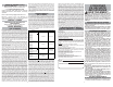
EXTENSION CORDS
Grounded tools require a three wire extension
cord. Double insulated tools can use either a two
or three wire extension cord. As the distance from
the supply outlet increases, you must use a heavier
gauge extension cord. Using extension cords with
inadequately sized wire causes a serious drop in
voltage, resulting in loss of power and possible tool
damage. Refer to the table shown to determine the
required minimum wire size.
The smaller the gauge number of the wire, the greater
the capacity of the cord. For example, a 14 gauge
cord can carry a higher current than a 16 gauge cord.
When using more than one extension cord to make
up the total length, be sure each cord contains at
least the minimum wire size required. If you are using
one extension cord for more than one tool, add the
nameplate amperes and use the sum to determine
the required minimum wire size.
Guidelines for Using Extension Cords
• If you are using an extension cord outdoors, be sure
it is marked with the suffi x “W” to indicate that it is
acceptable for outdoor use.
• Be sure your extension cord is properly wired and in
good electrical condition. Always replace a damaged
extension cord or have it repaired by a qualifi ed
person before using it.
• Protect your extension cords from sharp objects,
excessive heat and damp or wet areas.
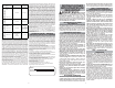
Recommended Minimum Wire Gauge
For Extension Cords*
Extension Cord Length
Nameplate
Amperes
25' 50' 75' 100' 150'
0 - 2.0
2.1 - 3.4
3.5 - 5.0
5.1 - 7.0
7.1 - 12.0
12.1 - 16.0
16.1 - 20.0
18
18
18
18
16
14
12
18
18
18
16
14
12
10
18
18
16
14
12
10
--
18
16
14
12
10
--
--
16
14
12
12
--
--
--
* Based on limiting the line voltage drop to fi ve volts at 150%
of the rated amperes.
READ AND SAVE ALL INSTRUCTIONS
FOR FUTURE USE.