
Operator's Manual S/N K45A


3
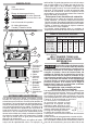
FUNCTIONAL DESCRIPTION
1. Wiring Cover
2. Cover
Release
Button
3. Cable
4. Wire Strain
Relief
5. Cable Clamp
6. AC Input/
Output
7. Pad Lock
8. LED Cover
1
2
3
4
8
7
5
6
ASSEMBLY
WARNING
To reduce the risk of injury, always
unplug tool before changing or
removing accessories. Only use accessories
specically recommended for this tool. Others
may be hazardous.
Wiring
WARNING
Always install light in accordance
with local codes.
To add lights in a chain, or replace the wiring:
1. Unplug the light.
2. Open the wiring cover by pushing the cover re-
lease button with the tip of a screwdriver.
3. To add wiring, expose 3 to 4 inches of the wires
from the outer jacket/armor.
4. Feed the wire through the AC input/output holes, and
butt the outer jacket/armor up against the wire clamps.
5. Tighten the wire clamps using the clamping screws.
Hand tighten wire clamp screws securely to 8 lb-in.
6. Wire the lamp according to the diagrams below.
Hand tighten terminal block screws securely to
10 lb-in.
7. Close the wiring cover securely.
GROUNDING
DANGER
Improperly connecting the ground-
ing wire can result in the risk of
electric shock. Check with a qualied electrician if
you are in doubt as to whether the outlet is prop-
erly grounded. Do not modify the plug provided
with the tool. Never remove the grounding prong
from the plug. Do not use the tool if the cord or
plug is damaged. If damaged, have it repaired by a
MILWAUKEE service facility before use. If the plug
will not t the outlet, have a proper outlet installed
by a qualied electrician.
Grounded Tools
Tools with Three Prong Plugs
Tools marked “Grounding Required” have a three
wire cord and three prong grounding plug. The plug
must be connected to a properly grounded outlet
(See Figure A). If the tool should
electrically malfunction or break
down, grounding provides a low
resistance path to carry electricity
away from the user, reducing the
risk of electric shock.
The grounding prong in the plug
is connected through the green wire inside the
cord to the grounding system in the tool. The green
wire in the cord must be the only wire connected
to the tool's grounding system and must never be
attached to an electrically "live" terminal. Your tool
must be plugged into an appropriate outlet, properly
installed and grounded in accordance with all codes
and ordinances. The plug and outlet should look like
those in Figure A.
SYMBOLOGY
Volts
Alternating Current
Electrical Shock Hazard
Read Operator's Manual
CAUTION
Do not stare at the
operating light source
C
US
UL Listing for Canada and U.S.
SPECIFICATIONS
Cat. No. .................................................... 2156-AC
Wiring .................................................3 Prong Plug
Cat. No. ..................................................... 2156-TL
Wiring .........................3 Prong L5-20P and L5-20R
Cat. No. ....................................................2156-MC
Wiring ................................................ 3 Wire Leads
AC Input Volts .............................................110-277
AC Input Watts ..................................................130
AC Output Volts ..........................................110-277
Max Terminal Block Ampacity ........................... 15A
Consult with Local and National Electrical Codes
Fig. A