
Use and Care Manual

3
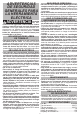
SYMBOLOGY
Volts
Direct Current
Alternating Current
Double Insulated
C
US
CAUTION
Do Not Stare Into Light
SPECIFICATIONS
Cat. No. ..................................................... 2144-20
M18™
Charger TypeM18™
DC Input Volts18
AC Input Volts120
AC Input Amps
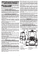
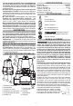
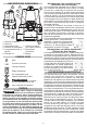
GROUNDING
DANGER
Improperly connecting the ground-
ing wire can result in the risk of
electric shock. Check with a qualied electrician
if you are in doubt as to whether the outlet is
properly grounded. Do not modify the plug pro-
vided with the tool. Never remove the grounding
prong from the plug. Do not use the tool if the
cord or plug is damaged. If damaged, have it
repaired by a MILWAUKEE service facility before
use. If the plug will not t the outlet, have a
proper outlet installed by a qualied electrician.
Grounded Tools (Three-Prong Plugs)
must be connected to a properly grounded outlet
-
function or break down, grounding provides a low
resistance path to carry electricity away from the
The grounding prong in the plug is connected through
the green wire inside the cord to the grounding
system and must never be attached to an electrically
Your tool must be plugged into an appro-
Fig. A
priate outlet, properly installed and
grounded in accordance with all codes
Double Insulated Tools (Two-Prong Plugs)
-
applicable standards of Underwriters
Fig. B
Fig. C
-
dard Association and the National Elec-
be used in either of the 120 volt outlets
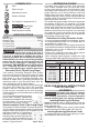
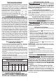
EXTENSION CORDS
Grounded tools require a three wire extension
the supply outlet increases, you must use a heavier
inadequately sized wire causes a serious drop in
voltage, resulting in loss of power and possible tool
The smaller the gauge number of the wire, the greater
When using more than one extension cord to make
up the total length, be sure each cord contains at
one extension cord for more than one tool, add the
nameplate amperes and use the sum to determine
Guidelines for Using Extension Cords
• If you are using an extension cord outdoors, be sure
• When stringing lights together, consider the total
Recommended Minimum Wire Gauge
For Extension Cords*
Extension Cord Length
Nameplate
Amperes
18
18
18
18
16
14
12
18
18
18
16
14
12
10
18
18
16
14
12
10
--
18
16
14
12
10
--
--
16
14
12
12
--
--
--
READ AND SAVE ALL INSTRUCTIONS
FOR FUTURE USE.
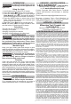
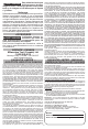
ASSEMBLY
WARNING
Recharge only with the charger
specied for the battery. For spe-
cic charging instructions, read the operator’s
manual supplied with your charger and battery.
Inserting/Removing the Battery
Insert the battery pack by sliding battery pack into
To remove the battery pack, press in both battery
Inserting/Removing Extension Cords
-