
Service Parts List S/N B56B

25
26 27 28 29 30 31 32 33
34 36 37 38 39 40 41
15
16 17
18 19
20
21 22
23
43
4 44
45 46
26
27 28 29 30
31 32 33 34
28
29 30 31
32 33 34
7
8 9 10 11
12 13 14
*
MILWAUKEE ELECTRIC TOOL CORPORATION
13135 W. Lisbon Road, Brookfi eld, WI 53005
Drwg. 3
BULLETIN NO.
54-40-6511
SERVICE PARTS LIST
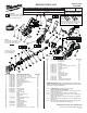
FIG. PART NO. DESCRIPTION OF PART NO. REQ.
1 06-82-2395 M2.6 x 10 Pan Hd. T-9 Screw (3)
2 06-82-2385 M2.6 x 14 Pan Hd. T-9 Screw (5)
3 06-82-2380 8-32 x 1/2" Pan Hd. Tapt. T-20 Screw (2)
4 10-20-0304 Fuel Gauge Label (1)
5 10-15-0955 Warning Label (1)
6 12-20-2421 Service Nameplate Kit (1)
7 14-46-1011 Steel Quik-Lok Blade Clamp (1)
8 31-15-0511 Spring Cover (1)
9 42-50-0076 Front Cam (1)
10 42-50-0077 Rear Cam (1)
11 45-22-0081 Sleeve (1)
12 34-60-3680 Retaining Ring (1)
13 40-50-0161 Torsion Spring (1)
14 44-60-0626 Lock Pin (1)
15 23-30-0020 Motor Assembly (1)
16 --------------- Motor (1)
17 --------------- Motor Mounting Plate (1)
18 --------------- Ball Bearing (1)
19 --------------- Pinion (1)
20 23-66-0315 Switch & PCB Assembly (1)
21 --------------- Terminal Block (1)
22 --------------- Switch (1)
23 --------------- PCB Assembly (1)
25 28-14-0030 Gearcase Assembly (1)
26 14-30-0035 Gearcase Set (1)
27 --------------- Left Gearcase (1)
28 14-30-0925 Right Gearcase Kit (1)
29 --------------- Right Gearcase (1)
30 --------------- 6-32 x 1/4" Pan Hd. Slt. T-15 Screw (3)
CATALOG NO. 2420-20
REVISED BULLETIN
54-40-6510
SPECIFY CATALOG NO. AND SERIAL NO. WHEN ORDERING PARTS
M12™ Hackzall
®
STARTING
SERIAL NO.
DATE
Feb. 2014
WIRING INSTRUCTION
B56B
EXAMPLE:
Component Parts (Small #)
Are Included When Ordering
The Assembly (Large #).
0
00
SEE REVERSE SIDE
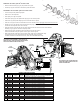
FIG. LUBRICATION (*See lubrication note above)
(Type 'J' Grease, No. 49-08-4220):
19,32 Completely coat all of the teeth of the Pinion (19) and Bevel
Gear (32) with grease.
27,29 Place a small amount of grease in Gearcase cavities.
33,34 Lightly coat the Drive Pin (33) and I.D. and O.D. of Bearing
Sleeve (34) with grease.
37 Place a dab of grease in the side slot and the rear pocket of
Spindle (37).
37,39 Lightly coat the O.D. of Spindle (37) and I.D. of Bushing (39)
with grease.
40,41 Saturate Felt (40) with lightweight oil prior to assembly with
Cap (41) onto Bushing (39) and Spindle (37).
FIG. PART NO. DESCRIPTION OF PART NO. REQ.
31 --------------- Ball Bearing (1)
32 --------------- Bevel Gear (1)
33 --------------- Drive Pin (1)
34 44-86-0085 Bearing Sleeve (1)
36 06-82-5320 8-32 x 5/8" Pan Hd Slt. T-20 Screw (6)
37 38-50-0015 Spindle (1)
38 06-65-0070 Spindle Guide Pin (1)
39 42-40-0120 Bushing (1)
40 45-06-0035 Felt (1)
41 44-86-0095 Cap (1)
43 31-44-0115 Handle Set (1)
44 --------------- Right Handle Halve (1)
45 --------------- Left Handle Halve (1)
46 --------------- Fuel Guage LED (1)
47 45-16-0040 Shoe (1)
48 45-24-0150 Shuttle (1)
49 42-70-0055 Housing Connection Clip (1)
50 42-55-2420 Carrying Case, Optional (1)
Lock Pin (14) to be
coated with graphite
prior to assembly.
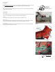
NOTE:
Clean bevel gear assembly
[29,30,31,32 & 33] with a clean,
dry cloth. DO NOT wash up.
* LUBRICATION NOTE: When servicing the Gears (19 & 32) or the
Gearcase Assembly (25), 90-95% of the old grease must be removed
prior to new 'J' grease being added.
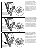
42-70-0058
Improved
Design
Original
Design
42-70-0055
*
M12™ tools utilize two different Housing
Connection Clip designs depending on the
Handle Set . See page two for details.