
Use and Care Manual


WIRING SPECIFICATIONS
Wire Wire Origin or
No. Color Part No. Gauge Length Terminals, Connectors and End Wire Preparation
1 Red 23-66-2645 ----- ----- Component of PCBA on Switch Assembly. Solder to right terminal on motor (marked with red dot).
2 Black 23-66-2645 ----- ----- Component of PCBA on Switch Assembly. Solder to left terminal on motor.
3 Red 23-66-2645 ----- ----- Component of PCBA on Switch Assembly. Attached to PCBA and wire #5 on connector block.
4 Black 23-66-2645 ----- ----- Component of PCBA on Switch Assembly. Attached to PCBA and connector block.
5 Red 23-66-2645 ----- ----- Component of Switch Assembly. Attached to switch and wire #3 at the connector block.
6a Orange 23-66-2645 ----- ----- Component of Switch Assy. Part of a 5 wire terminal block connecting to the PCBA and switch.
6b Green 23-66-2645 ----- ----- Component of Switch Assy. Part of a 5 wire terminal block connecting to the PCBA and switch.
6c White 23-66-2645 ----- ----- Component of Switch Assy. Part of a 5 wire terminal block connecting to the PCBA and switch.
6d Brown 23-66-2645 ----- ----- Component of Switch Assy. Part of a 5 wire terminal block connecting to the PCBA and switch.
6e Blue 23-66-2645 ----- ----- Component of Switch Assy. Part of a 5 wire terminal block connecting to the PCBA and switch.
7a Yellow 23-66-2645 ----- ----- Comp. of Switch Assy. Part of a 6 wire terminal block connecting to the PCBA and connector block.
7b White 23-66-2645 ----- ----- Comp. of Switch Assy. Part of a 6 wire terminal block connecting to the PCBA and connector block.
7c Blue 23-66-2645 ----- ----- Comp. of Switch Assy. Part of a 6 wire terminal block connecting to the PCBA and hall sensor.
7d Red 23-66-2645 ----- ----- Comp. of Switch Assy. Part of a 6 wire terminal block connecting to the PCBA and hall sensor.
7e White 23-66-2645 ----- ----- Comp. of Switch Assy. Part of a 6 wire terminal block connecting to the PCBA and hall sensor.
7f Black 23-66-2645 ----- ----- Comp. of Switch Assy. Part of a 6 wire terminal block connecting to the PCBA and hall sensor.
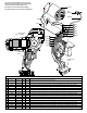
AS AN AID TO REASSEMBLY, TAKE NOTICE OF
WIRE ROUTING AND POSITION IN WIRE GUIDES
AND TRAPS WHILE DISMANTLING TOOL.
BE CAREFUL AND AVOID PINCHING WIRES
BETWEEN HANDLE HALVES WHEN ASSEMBLING.
2
1
3
3
4
4
5
MOTOR
HALL
SENSOR
SLEEVE
SWITCH
CONNECTOR
BLOCK
PCBA
6a
6b
6c
6d
6e
7e
7d
7f
7b
7a
7c
Orange
Green
White
Brown
Blue
Blue
White
Red
Black
White
Yellow
Red
Black
Red
Black
Red
= WIRE TRAPS
or GUIDES
Wire tie