
Service Parts List S/N E34A
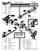

#4
Clutch Yoke
#26
Washer
#1
Retaining
Ring
#3
Return Spring
#5 Slide Clutch
#70
Clutch Gear
Assembly
#72
Gearcase
Assembly
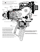
INSTALLING/REMOVING CLUTCH COMPONENTS
FROM GEARCASE ASSEMBLY
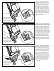
#39
Speed
Dial
#38
Left
Housing
Slot for light pipe
Slot for PCB assembly
#37 Clip
#47
Light Pipe
#50
PCB Assembly
Insert speed dial #39 into hole at rear of left housing halve #38. Secure dial
with clip #37. Set dial to the '1' position at the arrow in the housing. Speed
dial will turn in a counterclockwise direction.
Align board edges of PCB assembly #50 and the face plate edges of the
light pipe #47 with the slots in the housing halve.
Carefully insert the PCB assembly and light pipe into the slots. Route the
blue and black wires from the PCBA (for the EOT switch #74) into the wire
trap of handle halve above motor. Align the double fl ats of the speed dial
with the double fl ats in the hole of the potentiometer. Gently apply pressure
to engage shaft of speed dial in hole of potentiometer. Press and fully seat
PCBA and light pipe in the handle halve.
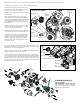
NOTE: Clutch Yoke #4 is to be the fi rst clutch component installed and the last component removed from the gearcase assembly.
Install side pins of clutch yoke #4 into the pivot sockets of the gearcase.
Insert slide clutch #5 onto clutch yoke with raised
driving lugs of the slide clutch oriented as shown.
Lugs are to face clutch gear assembly #70.
Place the return spring #3 into the recessed pocket
of the gearcase.
While holding slide clutch in place on the clutch
yoke, gently pivot the two parts into the clutch/gear
cavity of gearcase. NOTE: the slide clutch may have
to be slightly lifted out of place on the yoke during
the pivoting process to avoid any interference with
the cavity walls.
Be sure return spring is still in place in the recess
pocket of gearcase when the clutch yoke and slide
clutch are completely pivoted in place.
Press clutch yoke lever to assure proper operation
in pocket. If spring comes out of recess, start over.
Hold the lever of the clutch yoke completely down
to draw in the return spring and slide clutch. Place
shaft of the clutch gear assembly #70 through the
holes in the slide clutch and gearcase assembly.
Secure the clutch gear assembly with washer #26
and retaining ring #1.
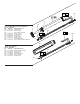
LUBRICATION NOTES:
Type ‘P’ Grease
No. 49-08-4250, 1.5 oz. / 42g tube
Prior to reinstalling, clean gear assemblies
with a clean, dry cloth. Lightly coat all parts
highlighted here with ‘P’ grease.