
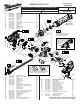
Service Parts List S/N E34A
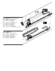
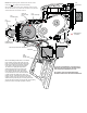

= WIRE TRAPS
or GUIDES
#47
Light Pipe
#50
PCB Assembly
Potentiometer of
PCB Assembly
#75
Motor Assembly
#48
Battery
Contact Plate
#74
EOT Switch
#49 Switch
NOTE: When replacing motor, unsolder wires from the motor
terminals, NOT the printed circuit board assembly.
When installing a new service motor assembly, orient the motor
with the red dot to the top. Solder the red wire to the top terminal
and the white wire to the bottom terminal.
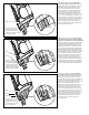
Watch for pinched wires here
When reassembling handle halves, it is critical to
have all wires securely seated in all of the wire
traps. It is suggested that the right handle halve
be placed over the left squarely with emphasis
on the slots for the light pipe and the PCBA.
The tension from spring #32 will push the
shuttle lock #24 forward and not inline with
the corresponding hole in the right handle
halve. With the handle halves almost closed,
use an instrument such as a small screwdriver
or probe to push the shuttle lock in place and
through the hole. Carefully bring the handle halves
together. Check for the free movement of the switch,
shuttle lock and speed dial prior to securing with handle
screws #14 and the housing connection #65. Insert a battery
pack and check for the proper operation of the tool.
Watch for
pinched wires
here
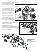
AS AN AID TO REASSEMBLY, TAKE NOTICE OF
WIRE ROUTING AND POSITION IN WIRE GUIDES
AND TRAPS WHILE DISMANTLING TOOL.
BE CAREFUL AND AVOID PINCHING WIRES
BETWEEN HANDLE HALVES WHEN ASSEMBLING.