
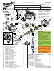
Service Parts List


SERVICE NOTES:
It is recommended that the Nylon Lock
Nut (25) be replaced if it is removed for
servicing the tool. See torque chart on
page two for proper setting.
The three Steel Balls (31) should be
replaced if replacing the Bevel Gear
Assembly (30) or the Hammer (32).
Place a few drops of thread locking
sealant to the threads of Sleeve (4).
Torque to 10 ft-lbs.
6x
1x
4x
2x
2x
3x
2x
2x
39
54
31
32
11
7
6
5
4
3
30
27
34
33
35
24
26
25
36
38
16
22
42
28
13
50
16
43
44
45
46
49
55
52
51
56
48
41
40
40 41
42 54
1
46 47 48 51
52 55 56
2
2x
19
47
24
38
8
57
4x
19
22
23
58
LUBRICATION:
Use Type ‘T’ Grease, No. 49-08-4260
Apply a thin coat of grease to all parts
shown in green.
Place a heavier amount to to the Ball
recesses and the gear teeth of the
Bevel Gear Assembly (30).
Place a heavier amount to to the Ball
recesses and the striking surfaces of
the Hammer (32).
Apply a heavier amount of grease to
the teeth of the pinion gear of the
Motor/ Diaphragm Assembly (23) and
to the teeth of the corresponding gear
and the pinion of the Bevel Pinion
Assembly (13).
LUBRICATION:
Use Type ‘Y’ Grease, No. 49-08-5270
Apply a thin coat of grease to the
bottom surface of the Switch Lockout
(43).
Place a dab of grease in the round
cavity of the On Button (49) to help
hold Spring (50) in place.
MILWAUKEE ELECTRIC TOOL CORPORATION
13135 W. Lisbon Road, Brookfi eld, WI 53005
Drwg. 5
BULLETIN NO.
54-43-2400
SERVICE PARTS LIST
FIG. PART NO. DESCRIPTION OF PART NO. REQ.
1 31-44-0980 Housing Halve Assembly (1)
2 23-66-2375 Switch Assembly (1)
3 44-40-0790 Collet Assembly (1)
4 45-22-0780 Sleeve (1)
5 34-40-0310 O-Ring (1)
6 40-50-1490 Sleeve Spring (1)
7 45-88-3110 Curved Washer (1)
8 14-29-0700 Gearcase Assembly (1)
11 14-73-0340 Anvil Assembly (1)
13 32-40-2400 Bevel Pinion Assembly (1)
16 05-78-0105 M4 x 10 Pan Hd. Tapt. T-20 ST Screw (6)
19 05-81-1140 M3 x 16 Screw (2)
22 45-88-1980 Spring Washer (2)
23 14-50-0710 Motor/Diaphragm Assy. (w/ needle bearing) (1)
24 ---------------- Left Gearcase Halve (1)
25 06-57-0625 Nylon Lock Nut (1)
26 45-88-3120 Washer (1)
27 45-88-3130 Thrust Washer (2)
28 02-80-1820 Thrust Bearing (1)
30 32-05-0650 Bevel Gear Assembly (1)
31 02-02-1300 5.0 Steel Ball (3)
32 45-56-5400 Hammer (1)
33 40-50-0860 Conical Spring (1)
34 45-88-3140 Core Shaft Washer (1)
35 02-02-0165 3.0 Steel Ball (21)
36 45-08-0625 Core Shaft (1)
38 --------------- Right Gearcase Halve (1)
39 05-81-1410 M4 x 16 Pan Hd. T-20 Screw (4)
40 05-81-1420 M3 x 10 Pan Hd. Plastite T-10 Screw (1)
41 06-82-1080 M3 x 14 Pan Hd. Plastite T-10 Screw (6)
42 --------------- Right Housing Halve (1)
43 44-20-1210 Switch Lockout (1)
CATALOG NO. 2458-20
REVISED BULLETIN
SPECIFY CATALOG NO. AND SERIAL NO. WHEN ORDERING PARTS
M12™ Palm Nailer
STARTING
SERIAL NO.
DATE
July 2013
WIRING INSTRUCTION
C70A
EXAMPLE:
Component Parts (Small #)
Are Included When Ordering
The Assembly (Large #).
0
00
See Reverse Side
FIG. PART NO. DESCRIPTION OF PART NO. REQ.
44 02-02-1100 4.0 Steel Ball (1)
45 40-50-1240 Spring (1)
46 44-34-0460 Switch Mount (1)
47 --------------- Switch (1)
48 44-90-0980 E-Ring (2)
49 42-42-0870 On Button (1)
50 40-50-2180 On Button Spring (1)
51 --------------- Battery Terminal Block (1)
52 --------------- PCB Assembly (1)
54 --------------- Left Housing Halve (1)
55 44-50-1450 Pin (2)
56 45-88-3150 Washer (2)
57 42-55-3100 Soft Cover Carrying Case (1)
58 45-56-2700 Hand Strap with Steel Ring (1)
12-20-2458 Service Nameplate (Not Shown) (1)