
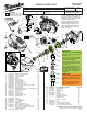
Service Parts List


= WIRE TRAPS
or GUIDES
3
4
BLUE
RED
SWITCH
(Back View)
BATTERY
TERMINAL
BLOCK
5
3
6
7
RED
MOTOR
(Back View)
2
WHITE
1
RED
Place motor in the
left handle halve
with the positive
terminal (marked
with a red dot) to
the bottom.
1
4
7
5
6
8
9
2
10
BLACK
WHITE
BLUE
RED
SLEEVE
RED
WHITE
BLACK
BLUE
Five wire sleeve from the
fuel gauge. Plugs into bottom
of PCB assembly.
Wires #8 and #9
to the LED.
1 Red ----- ----- Component of the Switch Assembly 23-66-2375.
2 White ----- ----- Component of the Switch Assembly 23-66-2375.
3 Red ----- ----- Component of the Switch Assembly 23-66-2375.
4 Blue ----- ----- Component of the Switch Assembly 23-66-2375.
5 Black ----- ----- Component of the Switch Assembly 23-66-2375.
6 Red ----- ----- Component of the Switch Assembly 23-66-2375.
7 White ----- ----- Component of the Switch Assembly 23-66-2375.
8 Black ----- ----- Component of the Switch Assembly 23-66-2375.
9 Blue ----- ----- Component of the Switch Assembly 23-66-2375.
10 Sleeve ----- ----- Fuel Gauge is a component of the Left Handle Halve.
Terminals, Connectors and 1 or 2 End Wire Preparation
Wire
Color
Origin or
Gauge
Wire
No.
Length
WIRING SPECIFICATIONS
AS AN AID TO REASSEMBLY,
TAKE NOTICE OF WIRE ROUTING
AND POSITION IN WIRE GUIDES
AND TRAPS WHILE DISMANTLING
TOOL.
BE CAREFUL AND AVOID PINCHING
WIRES BETWEEN HANDLE HALVES
WHEN ASSEMBLING.
Seat Torque
Fig. Part No. (in-lbs.)
16 05-78-0105 19-22
19 05-81-1140 7-10
25 06-57-0625 68-72
39 05-81-1410 19-22
40 05-81-1420 3-4
41 06-82-1080 3-6
SCREW TORQUE SPECS