
Service Parts List
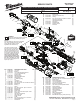


2466-20
M12™ FUEL™ 1/2" DIGITAL TORQUE WRENCH
Sep. 2019
FIG. PART NO. DESCRIPTION OF PART NO. REQ.
1 45-98-0070 1/2" Yoke (1)
2 42-40-0014 Bushing (1)
3 36-17-0410 1/2" Crankshaft-Essentric End (1)
5a --------------- 1/2" Anvil Subassembly (1)
5b --------------- Friction Plate (1)
5c 34-60-0995 Retaining Ring (1)
7 36-17-0415 Crankshaft-Spline End (1)
8 42-38-0283 Rubber Boot (1)
9 --------------- 'C' Retaining Ring (1)
10 --------------- Pin (2)
11 --------------- 1/2" Beam (1)
13 42-92-0667 Gear Box Cover (1)
14 05-81-1260 M4 x 10mm Pan Hd. T-20 Machine Screw (2)
23 02-04-0625 Ball Bearing (1)
25 42-40-0210 Bushing (1)
26 --------------- Stator (1)
28 06-82-2310 M3 x 8mm Pan Hd. Tapt. T-10 Screw (3)
29 44-86-1405 Bearing Plate (1)
30 02-04-0303 Ball Bearing (1)
31 44-66-1008 Motor Plate (1)
32 05-84-0200 M2.5 x 31mm Socket Cap Hd. Screw (3)
33 05-55-0047 Flange Nut (1)
34 --------------- Top Housing Assembly (1)
35 --------------- Light Pipe Cover (1)
36 --------------- Screen Holder (1)
37 --------------- PCBA (1)
38 06-82-3002 M3 x 10mm Pan Hd. ST T-10 Screw (7)
39 --------------- Rubber Button Pad (1)
41 --------------- Insert Base (1)
54-47-0480
REVISED BULLETIN
SERVICE PARTS
BULLETIN NO.
WIRING INSTRUCTION
DATE
CATALOG NO.
SPECIFY CATALOG NO. AND SERIAL NO. WHEN ORDERING PARTS
SERIAL
NUMBER
EXAMPLE:
Component Parts (Small #) Are Included
When Ordering Assembly (Large #).
0
00
K80A
See Page 2
FIG. PART NO. DESCRIPTION OF PART NO. REQ.
42 --------------- Insert Cover (1)
44 42-70-0058 Housing Connector Clip (1)
45 34-40-0180 O-Ring (2)
48 05-78-0105 M4 x 10mm Pan Hd. Taptite T-20 Screw (9)
49 --------------- Housing Cover-Right (1)
50 --------------- Housing Support-Left (1)
51 44-60-0575 Spring Pin (1)
52 44-10-0745 Switch Paddle (1)
53 42-42-0033 Switch Lock-Out (1)
54 --------------- Insert Rib (1)
FIG. PART NO. DESCRIPTION OF PART NO. REQ.
55 05-81-1337 M4 x14mm Pan Hd. T-20 Machine Screw (4)
56 45-22-0105 Motor Sleeve (1)
59 12-20-1466 Service Nameplate (1)
60 42-06-0005 1/2" Anvil Assembly (1)
61 45-98-0010 1/2" Yoke Housing Assembly (1)
62 14-20-2466 Electronics Assembly (1)
63 31-44-2461 Top Housing Assembly-REM PCBA (1)
64 43-84-0025 Insert Assembly (1)
65 14-29-0017 Gearcase Assembly (1)
66 31-44-2463 Handle Housing Kit (1)
67 16-01-1035 Rotor Assembly (1)
68 45-60-0065 1/2" Beam Assembly (1)
69 31-21-0004 Door Kit (1)
70 44-66-0978 Motor Plate Assembly (1)
71 42-04-9105 'U' Joint Assembly (1)
72 42-55-2466 Blow Molded Carrying Case (Tool Only) (1)
MILWAUKEE TOOL
l
www.milwaukeetool.com
13135 W. LISBON RD., BROOKFIELD, WI 53005
Drwg. 2
1
2
3
61
5a 5b
5c
60
5a
5b
5c
7
11
8
71
9
10
(2x)
14
(2x)
65
13
55
(4x)
23
25
23
25
67
9 10
11
68
69
48
(9x)
34
36
39
56
37
34 35
36 39
63
49
38
(3x)
45
(2x)
42
41
51
52
44
50
38 41 42
44 45
64
32
(3x)
31
30
28
(3x)
33
35
29
26
53
54
38
(4x)
26
37
62
48 49 50 51 53
54 55 59 69
66
59
28 29
30 31
70
72
NOTES:
Prior to installing a new service nameplate
(59), apply isopropyl alcohol to handle
cover (49) with a clean, lint free
applicator and allowed to dry.
Use a thin blunt punch with
the same OD or a similiar tool
like a nishing nail with same
OD and the pointed tip ground
down to remove spring pin (51)
from handle halves (49 and 50)
and switch paddle (52). As an
aid, be sure to prop up that
corner end of wrench to sup-
port the tapping out of spring
pin. When reinstalling pin, align
the holes and carefully press or
tap the pin in place.