
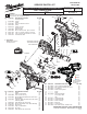
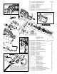
Replacement Parts List
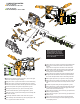

PCB ASSEMBLY
WIRING
SWITCH/
BATTERY
CONTACT
WIRING
MOTOR
WIRING
= WIRE TRAPS
or GUIDES
1
2
1
2
2
1
Red
White
3
3
4
4
5
6
7
6
7
8
10
9
8
9
10
11
12
1 RED PCB to motor positive (MTR+)
2 WHITE PCB to motor negative (MTR-)
3 RED PCB to switch (B+ SW)
4 BLACK PCB to negative battery contact (BAT-)
5 RED Switch to positive battery contact (BAT+)
6 RED PCB to battery contact (BAT+)
7 WHITE PCB to battery contact (BAT_ther)
8 YELLOW PCB to switch (ylw)
1
2
3
4
6
7
8
5
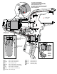
AS AN AID TO REASSEMBLY,
TAKE NOTICE OF WIRE ROUTING AND
POSITION IN WIRE GUIDES AND TRAPS
WHILE DISMANTLING TOOL.
BE CAREFUL AND AVOID PINCHING WIRES
BETWEEN HANDLE HALVES / BUSHINGS
WHEN ASSEMBLING.
Route red wire #1
over white wire #2
Route white wire #2
under all wires, specifically
black wire #4
Red wire #1 under
wires #8, #9 and
#10
2
4
9 BLACK PCB to switch (blk)
10 BLUE PCB to switch (blu)
11 BLACK PCB to LED (LED-)
12 BLUE PCB to LED (LED+)
10
9
11
12
11
12