
User Guide


4
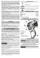
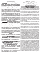
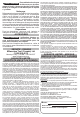
Using the Control Switch
The control switch may be set to three positions:
forward, reverse and lock. Due to a lockout mecha-
nism, the control switch can only be adjusted when
the ON/OFF switch is not pressed. Always allow the
motor to come to a complete stop before using the
control switch.
Push for
Forward
Push for
Reverse
PUSH TO CENTER TO LOCK
1. For forward (clockwise) rotation, push the control
switch in the direction shown. Check the direction
of rotation before use.
2. For reverse (counterclockwise) rotation, push the
control switch in the direction shown. Check the
direction of rotation before use.
3. To lock the trigger, push the control switch to the
center position. The trigger will not work when the
control switch is in the locked position.
Always remove the battery pack before performing
maintenance, changing accessories, storing the
tool and any time the tool is not in use.
Starting, Stopping and Controlling Speed
These tools may be operated at any speed from 0
to full speed.
1. To start the tool, pull the trigger.
NOTE: An LED is turned on when the trigger is
pulled.
2. To vary the driving speed, simply increase or
decrease pressure on the trigger. The further the
trigger is pulled, the greater the speed.
3. To stop the tool, release the trigger and the electric
brake stops the tool instantly.
Impacting Techniques
The longer a bolt, screw, or nut is impacted, the
tighter it will become. To help prevent damaging the
fasteners or workpieces, avoid excessive impact-
ing. Be particularly careful when impacting smaller
fasteners because they require less impacting to
reach optimum torque.
Practice with various fasteners, noting the length of
time required to reach the desired torque. Check the
tightness with a hand-torque wrench. If the fasteners
are too tight, reduce the impacting time. If they are
not tight enough, increase the impacting time.
Oil, dirt, rust or other matter on the threads or under
the head of the fastener affects the degree of tight-
ness.
The torque required to loosen a fastener averages
75% to 80% of the tightening torque, depending on
the condition of the contacting surfaces.
On light gasket jobs, run each fastener down to a
relatively light torque and use a hand torque wrench
for nal tightening.
of the tool. Make sure it latches securely into place.
WARNING
Only use accessories specically
recommended for this tool. Others
may be hazardous.
Use only sockets and other accessories speci-
cally designed for use on impact wrenches and
drivers. Other sockets and accessories might
shatter or break causing injury.
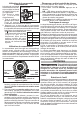
Attaching and Removing Accessories
Hex drive chuck
This driver is intended for use with drill
and driver bits with a 1/4" hex shank and
ball detent recess.
1. To attach an accessory, press the
shank into the hex drive chuck.
2. To remove the accessory, pull out
the ring and remove the accessory.
Release the ring.
OPERATION
WARNING
Always remove battery pack before
changing or removing accesso-
ries. Only use accessories specically recom-
mended for this tool. Others may be hazardous.
To reduce the risk of injury, always wear safety
goggles or glasses with side shields.
Fuel Gauge
To determine the amount of charge left in the bat-
tery, pull the trigger. The Fuel Gauge will light up for
2-3 seconds.
To signal the end of charge, 1 light on the fuel gauge
will ash for 2-3 seconds.
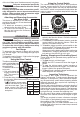
Using the Drive Control
The drive control button is
Speed
Indicator
Drive Control Button
Tapping Screw Mode
used to adjust the rota-
tion speed (RPM) for
the application.
To select the drive con-
trol mode:
1. Pull and release the
trigger to turn on the
tool. The current in-
dicator is lit.
2. Press the drive control button
to cycle through
the 4 modes. When the desired mode indicator is
lit, begin work.
* In
self tapping screw mode,
Mode RPM
1 0-1300
2 0-2400
3 0-3300
0-3300*
the tool will drive at full RPM
until the screw taps. Then, for
better control, the RPM will
slow as the screw seats to the
workpiece.