
Operator’s Manual


4
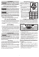
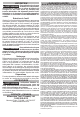
Using the Drive Control
The drive control button is used
Speed Indicator
Drive
Control
Button
Auto Shut
O Mode
to adjust the rotation speed
(RPM) for the application.
To select the drive control
mode:
1. Pull and release the trigger
to turn on the tool. The cur-
rent indicator is lit.
2. Press the drive control but-
ton to cycle through the
4 modes. When the desired
mode indicator is lit, begin
work.
*In auto shut o mode ,
Mode RPM IPM
1 0-1200 0-1100
2 0-1800 0-2100
3 0-2700 0-3200
0-2700* -
the tool will drive for-
ward at a reduced RPM
until the torque is
achieved. In reverse the
tool will operate at full
RPM to remove fasten-
ers at full torque.
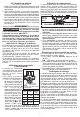
Using the Control Switch
The control switch may be set to three positions:
forward, reverse and lock. Due to a lockout mecha-
nism, the control switch can only be adjusted when
the ON/OFF switch is not pressed. Always allow the
motor to come to a complete stop before using the
control switch.
Push for
Forward
Push for
Reverse
PUSH TO CENTER TO LOCK
1. For forward (clockwise) rotation, push the control
switch in the direction shown. Check the direction
of rotation before use.
2. For reverse (counterclockwise) rotation, push the
control switch in the direction shown. Check the
direction of rotation before use.
3. To lock the trigger, push the control switch to the
center position. The trigger will not work when the
control switch is in the locked position.
Always remove the battery pack before performing
maintenance, changing accessories, storing the
tool and any time the tool is not in use.
Starting, Stopping and Controlling Speed
These tools may be operated at any speed from 0
to full speed.
1. To start the tool, pull the trigger.
NOTE: An LED is turned on when the trigger is
pulled.
2. To vary the driving speed, simply increase or
decrease pressure on the trigger. The further the
trigger is pulled, the greater the speed.
3. To stop the tool, release the trigger and the electric
brake stops the tool instantly.
ASSEMBLY
WARNING
Recharge only with the charger
specied for the battery. For spe-
cic charging instructions, read the operator’s
manual supplied with your charger and battery.
Removing/Inserting the Battery
To remove the battery, push in the release buttons
and pull the battery pack away from the tool.
WARNING
Always remove battery pack before
changing or removing accessories.
To insert the battery, slide the pack into the body
of the tool. Make sure it latches securely into place.
WARNING
Only use accessories specically
recommended for this tool. Others
may be hazardous.
Use only sockets and other accessories speci-
cally designed for use on impact wrenches and
drivers. Other sockets and accessories might
shatter or break causing injury.
Attaching and Removing Accessories
3/8" and 1/2" Friction Ring
(Cat. No. 2554-20 and 2555-20)
1. Use only the appropriate size Square Drive Sockets.
2. To attach a socket, align the accessory with the
anvil and push it rmly over the retaining ring.
3. To remove the accessory, pull the accessory o
the anvil.
1/2" Pin Detent
(Cat. No. 2555P-20)
1. Use only the appropriate size Square Drive Sockets.
2. To attach a socket, align the hole in the accessory
with the detent pin on the anvil. Hold the detent
pin in while pushing the socket onto the anvil.
The detent pin will snap into place in the hole to
secure the socket.
3. To remove the socket, insert a nail or other thin
object into the hole in the accessory and press
in the detent pin. Pull the accessory o the anvil.
OPERATION
WARNING
To reduce the risk of injury, always
wear proper eye protection marked
to comply with ANSI Z87.1.
Always remove battery pack before changing
or removing accessories. Only use accessories
specically recommended for this tool. Others
may be hazardous.
Fuel Gauge
To determine the amount of charge left in the battery,
turn the tool ON. The Fuel Gauge will light up for 2-3
seconds. When less than 10% of charge is left, 1 light
on the fuel gauge will ash 4 times.
To signal the end of charge, 1 light on the fuel gauge
will ash 8 times and the tool will not run. Charge
the battery pack.
If the battery becomes too hot, the fuel gauge lights
will ash in an alternating pattern and the tool will not
run. Allow the battery to cool down.