
Use and Care Manual


4
5
ASSEMBLY
WARNING Recharge only with the
charger specifi ed for the battery. For specifi c
charging instructions, read the operator’s
manual supplied with your charger and battery.
Inserting/Removing the Battery
To remove the battery, push in the release buttons
and pull the battery pack away from the tool.
To insert the battery, slide the pack into the body of
the tool. Make sure it latches securely into place.
WARNING Always remove battery pack
before changing or removing accessories.
Only use accessories specifi cally recommend-
ed for this tool. Others may be hazardous.
OPERATION
WARNING Always remove battery
pack before changing or removing acces-
sories. Only use accessories specifically
recommended for this tool. Others may be
hazardous.
WARNING To reduce the risk of injury,
wear safety goggles or glasses with side
shields.
Dust Collection
Switch the exhaust selector to the left or right,
depending on your job. Use the accessory dust
bag (Cat. No. 42-16-2623) or a connected, run-
ning vacuum when using the planer to keep the
workplace cleaner. Install the dust bag or a vacuum
hose (1-1/2" diam.) by twisting onto the selected
exhaust port. Always empty and clean the dust bag
thoroughly when it becomes about half-full and
upon completion of a job.
WARNING Dust from surface coatings
such as polyurethanes, linseed oil, etc., can
self-ignite. To reduce the risk of fi re, empty the
dust bag when it becomes about half-full and
never store or leave a planer without totally
emptying its dust bag. Also follow the recom-
mendations of the coatings manufacturers.
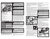
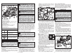
Blade
clamp
Blade
bolts
Blade
WARNING Blades are sharp and
fragile. Handle with care. Laceration and/or
damage to the blade can occur.
WARNING Always change/reverse
blades in pairs. Unpaired blades can cause
increases in vibration, loss of control, and
lower tool performance.
Installing/Replacing Blades
The planer blades have two cutting edges, and
may be reversed when one of the cutting edges
becomes dull or chipped. Do not sharpen planer
blades. Always change/reverse blades in pairs. Use
only 3-1/4", tungsten-carbide or carbide, double-
edged (reversible) planer blades.
To remove blades:
1. Remove battery pack.
2. Clean dust and debris from the blade drum.
3. Using the 1/8" hex wrench provided, loosen (do
not remove) the three blade bolts.
4. Using a scrap piece of wood, slide the old blade
out of the blade clamp.
NOTE: If the blade is diffi cult to remove, clean
the blade and blade clamp with alcohol, mineral
spirits, or lacquer thinner.
5. Rotate blade drum and repeat for other blade.
To install blades:
6. Reverse blades or use new blades.
7. Align the grove on the top of the blade with the
ridge of the blade clamp and carefully slide the
blade onto the drum.
8. Center the blade lengthwise - it will overhang the
blade clamp slightly on both sides.
9. Using a block of wood, push the blade back
towards the blade clamp so that the inner side
of the blade is pressed against the step on the
drum. This will ensure proper alignment and
reduce tool vibration.
10. Tighten all three blade bolts securely.
11. Rotate blade drum and repeat for other blade.
12. Once installed, rotate the blade drum to ensure
the blade does not contact the shoe or housing,
and that the blades are both installed straight.
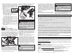
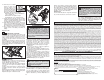
Adjusting the Depth of Cut
1. Remove battery pack.
2. Determine the amount of ma-
terial to be removed during
each pass of the planer. Take
into account the moisture and
hardness of the workpiece, as
well as the desired feed rate.
3. Each detent is 1/256" (0.1 mm).
Turn the knob clockwise to increase the depth of
cut, counterclockwise to decrease the depth of
cut. Do not change the depth of cut while planing.
4. Make a test cut. If the planer moves easily
through the workpiece, increase the depth of
cut. If the planer seems to strain, decrease the
depth of cut.
Installing the guide fence
Use the guide fence for additional stability when
cutting workpieces up to 3-1/4" wide, and when
beveling at up to a 45° angle.
1. Remove battery pack
2. Screw the guide fence into the left or right fence
insert.
3. Using the thumb screws, adjust the width and
bevel according to the job.
Closing the Kickstand
The kickstand is provide to protect the blade when
the tool is set down. It is pushed up automatically
during a normal planing operation. To close the kick-
stand manually, push closed and slide to the side.
Operation
1. Remove battery pack.
2. Check blades. Replace if necessary.
3. Install guide fence, if desired.
4. Turn the exhaust selector to the desired side.
Install dust bag or vacuum on appropriate side
of tool, if desired
5. Clamp work securely.
6. Insert battery pack.
7. Securely grasp the tool by the handle and the
depth adjustment knob.
8. Line up the front of the tool with the workpiece.
WITHOUT contacting the drum to the workpiece,
press down on the trigger lock-off and pull the
trigger. Wait for the tool to come to full speed
before beginning to avoid overloading and
damaging the tool.
9. Keeping the front shoe fl ush with the workpiece,
use gentle pressure to guide the planer. All
pressure should be on the front shoe when
starting the cut. Transfer downward pressure
to the rear shoe as it contacts the workpiece.
10. For best results, push plan-
er through the workpiece at
an even rate. Do not push
too fast as it will strain the
motor and could damage
the blades. Do not pull the
planer backward over the workpiece.
Slow feed + shallow depth of cut = smooth fi nish
Faster feed + deep depth of cut = rough fi nish
WARNING To reduce the risk of injury,
wear safety goggles or glasses with side
shields.
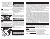
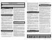
FUNCTIONAL DESCRIPTION
1. Handle
2. Trigger
3. Trigger lock-off
4. Exhaust ports
5. Exhaust selector
6. Depth knob
(grasping surface)
7. Chamfer groove
1
5
4
3
6
7
2
10
9
8
11
12
8. Fence insert
(both sides of tool)
9. Front shoe
10. Drive belt guard
11. Kickstand (not shown)
12. Rear shoe
13. Wrench storage
(not shown)
13