
Service and Repairs
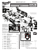

When servicing, remove 90-95%
of the existing grease prior to in-
stalling Type “J”. Original grease
maybe similar in color but not
compatible with “J”.
= WIRE TRAPS
or GUIDES
Terminal
Block
On-Off
Switch
PCBA
Motor Assembly
LED
Heat Shrink
Tubing
Magnet
Ring
Before securing the Right Rear Handle #22
and the Right Front Housing #32, be sure that
the LED wires are tucked completely down in
the wire trap. Be careful not to pinch the LED
wires in the area where the rear handles, front
housings and gearcase meet.
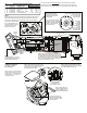
NOTE:
Terminal Block #11 must be
installed at the same time into
Terminal Block Plate #12.
Blue
Wire
Red Wire
Positive Motor
Terminal
Red
Wire
Blue Wire
+
NOTE:
Route the blue wire (from the PCBA to the negative motor terminal)
behind the PCBA screw lobe. Be sure to tuck the blue wire down
into the rear handle as much as possible, away from the magnet
ring of the motor assembly.
It is recommended to use
heat shrink tubing over the
soldered wires / motor
terminals as shown.
Positive motor terminal is surrounded
by a plastic ledging with a step
in it. Connect red
wire from PCBA
to this terminal.
The plastic
ledging
around the
negative
terminal has
no step.
Connect blue
wire from PCBA
to this terminal.
Proper orientation of the
Motor Assembly #63 is
with the slot in the motor
canister to the top at the
12:00 position.
This rear view of the motor
assembly is shown without
the rubber motor band #20
in place so the slot at the
top could be seen.
Slot
+
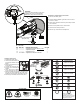
LUBRICATION NOTES:
Use Type 'J' Grease,
No. 49-08-4220
It is recommended to hand tighten Rear Handle Screws #16, PCBA
Screws #16 and Front Housing Screws #33 to prevent over tightening.
Exercise caution when tightening screws if a cordless driver drill is used.
SCREW TORQUE SPECIFICATIONS
SEAT TORQUE
FIG. PART NO. WHERE USED (KG/CM) (IN/LBS)
4 05-88-0045 Gearcase (Top) / Clip 13±2 11.5±1.5
16 06-82-1080 Rear Handle - Right 10±2 8.5±1.5
16 06-82-1080 PCBA 10±2 8.5±1.5
33 06-82-2385 Front Housing - Right 7±1 6±1
42 05-88-0400 Gearcase (Front) 21.5±2 18.5±1.5
Front View of #3
Quick Release Lever
Metal Cam
3
65
31
Place a light coating of grease on the
metal cam portion of the Quick Release
Lever #3 prior to installing on the
Gearcase Assembly #65.
Place a light coating of
grease on Metal Pin #31
prior to installing in the
Gearcase Assembly #65.
Fill the inside cavity of
Gearcase Assembly #65
with approximately .35oz.
(10g) of grease.
Place a light coating of grease on the
O-Rings #6 (both sides) prior to installing
in the Quick Release Lever #3.
6