
Use and Care Manual


5
ASSEMBLY
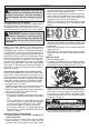
WARNING Recharge only with the
charger specied for the battery. For specic
charging instructions, read the operator’s
manual supplied with your charger and bat-
tery.
Inserting/Removing the Battery
To remove the battery, push in the release buttons
and pull the battery pack away from the tool.
To insert the battery, slide the pack into the body of
the tool. Make sure it latches securely into place.
Selecting Blade
Always use sharp blades. Dull blades tend to
overload the tool and increase the chance of
KICKBACK (see "Causes and Operator Prevention
of KICKBACK"). Only use thin kerf blades with a
maximum safe operating speed greater than the no
load RPM marked on the tool's nameplate. Read
the blade manufacturer's instructions before use.
Do not use any type of abrasive cut-off wheel or
dry diamond cutting blades. Use the correct blade
type for your application. Using the wrong blade
may result in reduced performance or damage to
the blade. Do not use blades that are cracked or
have broken teeth.
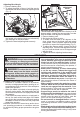
Checking the Operation of the Lower Guard
Check the operation and condition of the lower
guard lever. If the guard and the lever are not op-
erating properly, they must be serviced before use.
Lower guard may operate sluggishly due to dam-
aged parts, gummy deposits, or a buildup of debris.
1. Unplug tool before checking the lower guard.
2. Place the tool on its side.
NOTE: This procedure will not show proper lower
guard operation if the tool is not on its side.
3. Grasp the lower guard by the sides and push it
all the way back into the blade housing.
4. Release the lower guard.
• If the guard immediately springs back into place,
it is working correctly and you may continue with
use.
• If the guard does not immediate spring back
into place, clean the upper and lower guards
to remove all chips and debris. Then, check
the operation again by starting with step 1.
• If the guard still does not immediately spring
back into place, contact a MILWAUKEE service
facility for repairs.
Installing and Removing Blades
1. Remove battery pack before installing or
removing blades.
2. Place the saw on a at surface with the blade
facing upwards. To remove the bolt from the
spindle, push in the spindle lock button. While
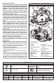
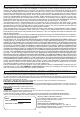
3. Raise or lower the shoe to the desired position.
Markings in 1/4" increments are located on the
inner side of the upper guard for depth setting.
For the proper depth setting, the blade should
extend no more than 1/8" to 1/4" below the mate-
rial being cut (Fig. 3).
holding in the spindle lock button, use the wrench
provided with the tool to turn the bolt clockwise.
Remove the bolt and blade ange.
3. Slide the lower guard lever up to raise the lower
guard. Remove the blade from the spindle. Al-
ways clean the spindle, upper guard and lower
guard to remove any dirt and sawdust.
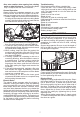
NOTE: Do not remove inner blade ange. Larger
diameter of inner ange (Fig. 1) should face the
blade.
1/4"
(
6 mm
)
Fig. 2
Fig. 3
WARNING Always remove battery
pack before changing or removing acces-
sories. Only use accessories specifically
recommended for this tool. Others may be
hazardous.
4. Lift the depth adjusting lever up towards the
motor housing to secure the shoe position.
4. To install a blade, place the blade on the spindle
with the teeth pointing in the same direction as
the arrow on the lower guard. Release the lower
guard lever.
5. Place the blade ange on the spindle and hand
tighten the bolt.
6. While holding in the spindle lock button, use the
wrench to turn the bolt counterclockwise and
tighten.
Adjusting Depth
1. Remove battery pack.
2. To adjust the depth of the cut, hold the saw by
the handle and loosen the depth adjusting lever
by pushing it down toward the shoe (Fig. 2).
Bolt
Outer ange
Inner ange
Spindle
Fig. 1