
Service Parts List S/N C07A

14
13
12
11
10
14
23
21
9
8
18
19
20
7
2
22
24
25
26
29
37
32
31
33
34
32
52
53
54
55
30
28
27
28
17
16
15
38
39
40
51
41
42
50
43
44
45
70
71
73
4
3
4
1
6
35
69
46
67
68
65
48
49
47
66
64
72
32
57
62
3
58
59
60
5.22
56
61
63
19
36
79
17 24 26
31 32 33
78
10 11 12
13 14
81
38 39
40 41
82
44 45
77 78
80
34 35
36 37
84
47 48 49 64
65 66 67
85
69
70
83
52
53
77
25
29
5.1 5.2 5.3 5.4 5.5 5.6
5.7 5.8 5.9 5.10 5.11
5
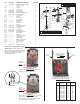
See next page for
components of this
assembly.
28
28
27
27
See next page
for service note
86
NOTE: Apply Loctite
®
277 or
equivalent to threads of
Screws [42].
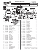
54-40-2645
CORDLESS M18 ORBITAL JIG SAW
Aug. 2013
2645-20
SEE PAGE 4
C07A
FIG. PART NO. DESCRIPTION OF PART NO. REQ.
1 42-92-1160 Blade Cover 1
2 43-54-0780 Guard Wire 1
3 05-81-1030 M4 x 9.0 T-20 Screw 2
4 05-81-1040 M4 x 16 T-20 Screw 3
5 14-20-4000 Gearcase Cover Assembly 1
5.22 05-81-1050 M4 Flat Head Screw 4
6 42-28-0450 Support Block 1
7 05-81-1060 M4 x 44 Pan Head T-20 Screw 2
8 43-44-0610 Gasket 1
9 02-50-1260 Needle Bearing 1
10 --------------- Blade Guide Holder 1
11 --------------- Blade Guide 1
12 --------------- Needle Bearing 1
13 --------------- 4.0 x 11 Pin 1
14 --------------- E-Ring 2
15 06-65-0410 5.0 x 23.5 Pin 1
16 06-65-0420 5.0 x 9.6 Pin 1
17 --------------- 5.0 x 22 Pin 2
18 05-81-1070 M4 x 12 Screw 2
19 45-88-1890 Spring Washer 3
20 34-60-0750 E-Ring 1
21 44-66-1510 Eccentricity Plate 1
22 44-66-1630 Drive Plate 1
23 42-28-0500 Counter Balance 2
24 --------------- 4 x 23 Pin 1
25 --------------- Output Gear 1
26 --------------- 8 x 43 Pin 1
27 05-81-1080 M4 x 25 Screw 2
28 05-81-1090 M4 x 24 Screw 2
29 --------------- Needle Bearing 2
30 45-88-3070 Washer 1
31 --------------- Rubber Knock 2
32 --------------- 2.5 x 7.5 Pin 3
33 --------------- Gearcase 1
34 34-60-0770 E-Ring 1
35 --------------- Orbital Adjustment Shaft 1
36 --------------- Orbital Adjustment Stop 1
37 --------------- Orbital Adjustment Lever 1
38 --------------- Spiral Pinion Shaft 1
39 --------------- Ball Bearing 1
REVISED BULLETIN
SERVICE PARTS LIST
BULLETIN NO.
WIRING INSTRUCTION
DATE
EXAMPLE:
Component Parts (Small #) Are Included
When Ordering The Assembly (Large #).
0
00
CATALOG NO.
SPECIFY CATALOG NO. AND SERIAL NO. WHEN ORDERING PARTS
SERIAL
NUMBER
MILWAUKEE ELECTRIC TOOL CORPORATION
13135 W. LISBON RD., BROOKFIELD, WI 53005
Drwg. 4
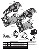
FIG. PART NO. DESCRIPTION OF PART NO. REQ.
40 --------------- Fan 1
41 --------------- Drive Coupler 1
42 05-81-1200 M5 x 8 Screw 2
43 44-34-0425 Motor Mount 1
44 --------------- Drive Pinion 1
45 --------------- 18V DC Motor 1
46 42-42-0700 Lock Button 1
47 --------------- 18V DC Switch 1
48 --------------- Red Leadwire 1
49 --------------- Black Leadwire 1
50 42-68-0880 Clamping Claw 1
51 43-56-0695 Airfl ow Baffl e 1
52 --------------- M6 x 31 Bolt 1
53 --------------- Fix Wedge 1
54 44-10-0700 Adjustable Base Lever 1
55 45-88-1990 Washer 1
56 28-06-1280 Adjustable Shoe 1
57 43-84-1030 Anti-Splintering Insert 1
58 42-92-1580 Slide Plate 1
59 05-88-1208 M4 x 13 Flat Head Screw 2
60 31-15-0690 Plastic Cover 1
61 31-17-0570 Shoe Retainer 1
62 05-59-0900 M6 x 7 Nut 1
63 45-88-2060 Washer 1
64 --------------- Red Leadwire 1
65 --------------- Black Leadwire 1
66 --------------- Connector Assembly 1
67 22-56-0025 Terminal Block Assembly 1
68 40-50-1090 Compression Spring 1
69 --------------- Support Housing (Left Handle Half) 1
70 --------------- Housing Cover (Right Handle Half) 1
71 05-86-1200 M4 x 16 Pan Head Plastite T-20 Screw 9
72 10-20-3795 Warning Label 1
73 12-20-1305 Service Nameplate Kit 1
77 32-30-0200 Gear Assembly 1
78 42-36-0280 Blade Guide Assembly 1
79 14-30-0980 Gearcase Assembly 1
80 30-58-0100 Orbit Lever Assembly 1
81 36-66-4490 Pinion Assembly 1
82 23-30-0780 Motor Assembly 1
83 30-58-0125 Tension Lever Assembly 1
84 23-66-2960 Switch Assembly 1
85 31-44-2375 Handle Halves Assembly 1
86 42-55-2645 Carrying Case, Optional 1