
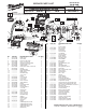
Service Parts List S/N C07A

TORQUE SPECIFICATIONS
Min. Max.
Fig. Part No. (In-Lbs) (In-Lbs)
3 05-81-1030 15 25
4 05-81-1040 15 30
5.7 05-86-0300 4 6
5.22 05-81-1050 15 25
5.30 --------------- 20 30
7 05-81-1060 7 15
18 05-81-1070 25 25
27 05-81-1080 15 25
28 05-81-1090 15 25
42 05-81-1200 20 30
59 05-88-1208 15 25
71 05-86-1200 7 15
FIG. PART NO. DESCRIPTION OF PART NO. REQ.
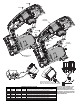
5 14-20-4000 Gearcase Cover Assembly 1
5.1 --------------- Gearcase Cover 1
5.2 --------------- Lever 1
5.3 --------------- Link Rod 1
5.4 --------------- 2.8 x 14 Pin 2
5.5 44-10-0690 Sleeve Lever 1
5.6 45-22-0190 Rotate Sleeve 1
5.7 05-86-0300 M3 x 22.5 Slotted Screw 1
5.8 40-50-4410 Tension Spring 1
5.9 --------------- 2.5 x 25 Pin 1
5.10 --------------- E-Ring 1
5.11 --------------- 4.0 x 30 Pin 1
5.12 --------------- Cover Plate 1
5.13 --------------- Rubber Seal 1
5.14 --------------- Felt Seal 1
5.15 --------------- Fiber Seal 1
5.16 --------------- Bushing 2
5.17 40-50-0780 Compression Spring 2
5.18 --------------- Saw Bar Guide 1
5.19 06-65-0310 5 x 46 Pin 1
5.20 44-74-0170 Pivot Post 2
5.21 44-66-1290 Pressing Plate 1
5.22 05-81-1050 M4 Flat Head Screw 2
5.23 --------------- Cover Plate 1
5.24 --------------- Saw Bar 1
5.25 --------------- Compression Spring 1
5.26 --------------- Clamp Plate 1
5.27 --------------- Torsion Spring 1
5.28 --------------- Blade Clamp Sleeve 1
5.29 --------------- Connecting Link 1
5.30 --------------- M4 x 10 Screw 2
5.31 --------------- Pin 1
76 38-50-0750 Spindle Assembly 1
5.19
5.24
5.20
5.23
5.21
5.22
5.14
5.13
5.25
5.26
5.27
5.28
5.16
5.18
5.17
5.1
5.16
5.15
5.11
5.10
5.12
5.9
5.8
5.7
5.2
5.3
5.4
5.5
5.6
5.30
5.29
5.31
5.1 5.2 5.3 5.4 5.5 5.6
5.7 5.8 5.9 5.10 5.11
5
5.12 5.13 5.14 5.15 5.16 5.18 5.23 5.24
5.25 5.26 5.27 5.28 5.29 5.30 5.31
76
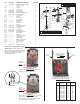
Counter
Balances (23)
Not Hitting
Steel Pin (17)
Counter Balances Installed
CORRECTLY
Counter Balances (23) do not come into contact
with Steel Pin (17) inside Gearcase (33).
Approximately .065 clearance between bottom
of Counter Balances and Steel Pin.
Counter
Balances (23)
Hitting
Steel Pin (17)
Counter Balances Installed
INCORRECTLY
Counter Balances (23) come into contact with
Steel Pin (17) inside Gearcase (33).
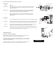
(27)
(28)
Screws (27 & 28)
must be reinstalled
and tightened
as shown.
10-11
Threads
5-6
Threads
Front View of Gearcase
Overall length of screws are identical
although length of threads are different
IMPORTANT: Place both of the Counter
Balance Blocks (23) into the Gearcase (33)
with the shorter fl at sides positioned to the
left side in the Gearcase (as viewed
from the front of tool).
23
Position short flat side
to the left as shown.
Service Notes for 2645 Cordless Jigsaw