
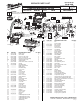
Service Parts List S/N C07A

2
4
3
4
5
Short
Screw
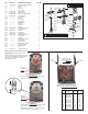
FIG. 3
Service Notes for 2645 Cordless Jigsaw - continued
Disassembly
FIG. NOTES:
18,19,20,21,26 Eccentricity Plate (21) Screws and Lock Washers (18-19) must be removed
prior to removing E-clip (20) from Gearcase Pin (26) to prevent damaging
the E-clip. See Fig. 1
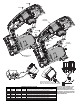
33,38,39,40,41 Remove Motor Pinion Assembly (81) from Gearcase (33) by placing a 3/32"
pin punch into the center counter bore of Pinion (38) and gently tapping
assembly until removed from Gearcase (33). See Fig. 2
1,5 Remove Plastic Blade Cover (1) from the Gearcase Cover (5) by gently
squeezing raised plastic tabs on both sides of cover simultaneously and
pulling forward.
Reassembly
42 Secure Motor Mount Plate Screws (42) with Blue Loctite
®
No. 44-22-0090 if removed.
18,19,20,21 E-clip (20) must be reinstalled onto Gearcase Pin (26) prior to installing Eccentricity
Plate (21) Screws and Lock Washers (18-19) to prevent damaging E-clip. See Fig. 1
22,23,33 Bevel side of Counter Balance Plates (23) must face Rocker Arm Plate (22) when
installed into Gearcase (33). (Reference assembly Illustration picture).
2,3,4,5,7,33 Reinstall Wire Guard (2) onto Gearcase (33) by positioning round prongs of guard
thru Gearcase cover (5) and place wires into round holes provided in Gearcase (33)
prior to securing Gearcase Screws (3-4-7). See Fig. 3
LUBRICATION NOTES:
Use Type 'J' Grease, No. 49-08-4220
When servicing, remove 90-95% of the existing grease prior to installing Type “J”.
Original grease maybe similar in color but not compatible with “J”
Coat internal components of Gearcase (33) with approx. 1/4 oz. grease (front and
back) prior to installing into Gearcase. (Lightly coat steel pins (17, 24, 26) inside
Gearcase prior to reassembly)
Coat internal components of Gearcase Cover (5) with approx. 1/8 oz. grease and
place another approx. 1/8 oz. grease in the top of the Gearcase Cover.
21
18
19
20
26
FIG. 1
33
38
39
40
41
81
38 39
40 41
FIG. 2
SEE PAGE 4 FOR WIRING
INSTRUCTIONS